Truss Point Load Calculator
Estimate a simply supported entertainment truss span with a main point load, distributed fixture load, self-weight, dynamic allowance, derating, sling angle factor, and left/right support reactions.
Planning note: These presets are realistic stage packages for early load conversations. Replace every value with the actual manufacturer load table, fixture weight, clamp weight, cable weight, and approved rigging plan.
Calculation Breakdown
| Case | Formula | Use In This Calculator | Rigging Meaning |
|---|---|---|---|
| Point Off-center point load | RA = P(L-a)/L, RB = Pa/L | Main fixture pod, speaker motor, scenic pick, or hoist at distance a. | The nearer support sees the larger reaction. |
| UDL Distributed load | W = wL, RA = RB = W/2 | Evenly spaced lighting, cable, pipe, soft goods, and truss self-weight. | Balanced only when the load is truly uniform. |
| Span Bending moment | M = P a(L-a)/L + wL²/8 | Combines the selected point load and distributed line load. | Compared as equivalent center point load, P = 4M/L. |
| Reaction Bridle leg | T = reaction / sin(angle) | Applies the sling angle factor to the largest support reaction. | Lower sling angles increase tension quickly. |
| Planning Table | Typical Span Points | Self-Weight Used | Important Boundary |
|---|---|---|---|
| 12 x 12 in plated box truss | 25, 30, 35, 40, 45, 50 ft | 5.6 lb/ft | Light-duty spans fall fast past 35 ft. |
| 20.5 x 20.5 in medium box truss | 30, 40, 50, 60, 70 ft | 9.6 lb/ft | Useful for longer audio or lighting spans. |
| 290 mm light box truss | 6, 8, 10, 12 m | 8.1 kg/m | Convert only if the exact brand table matches. |
| 400 mm medium box truss | 8, 10, 12, 14, 16 m | 12.8 kg/m | Check orientation, chord direction, and connectors. |
| 12 in triangular truss | 20, 25, 30, 35, 40 ft | 4.9 lb/ft | Orientation matters more than box truss. |
| Load Item | Planning Weight | Point Or Distributed | What To Verify |
|---|---|---|---|
| LED PAR with clamp and safety | 10-14 lb each / 4.5-6.4 kg | Distributed when evenly spaced | Yoke, half coupler, safety cable, and power tail. |
| Moving wash or spot | 35-65 lb each / 16-29 kg | Point-like unless spacing is dense | Base weight, omega brackets, clamps, and cable slack. |
| Small flown speaker with yoke | 45-85 lb each / 20-39 kg | Point load at bracket or motor | Rated yoke, secondary safety, and hardware stack. |
| Compact line array element | 55-90 lb each / 25-41 kg | Concentrated motor point | Frame, pins, motor, bridle, and manufacturer array limit. |
| Cable loom and Socapex style tails | 1.0-3.5 lb/ft / 1.5-5.2 kg/m | Distributed if tied along the span | Drop length, service loops, strain relief, and cable picks. |
| Angle From Horizontal | Tension Factor | Example Per 1000 lb Vertical | Planning Note |
|---|---|---|---|
| 90° | 1.000 | 1000 lb / 454 kg | Vertical leg, no angle increase. |
| 60° | 1.155 | 1155 lb / 524 kg | Common minimum target for many bridles. |
| 45° | 1.414 | 1414 lb / 641 kg | Leg tension rises sharply. |
| 30° | 2.000 | 2000 lb / 907 kg | Lower angles are generally not recommended. |
| Span Example | Center Point Load | UDL Total | Closest Use Case |
|---|---|---|---|
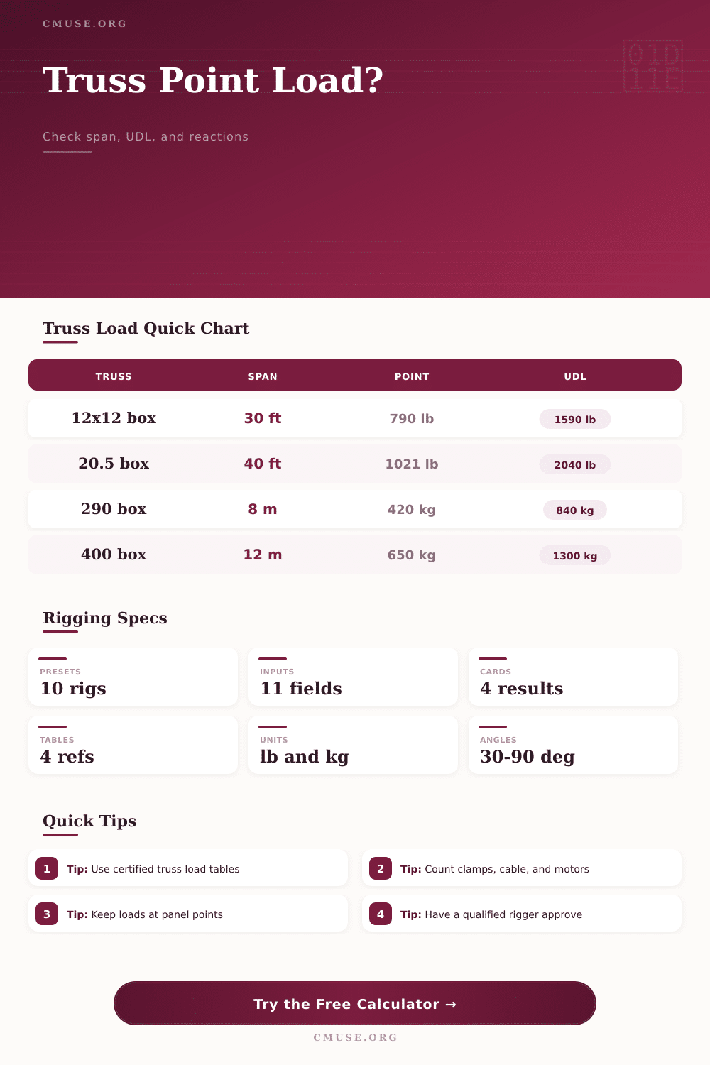
| 12 x 12 in box, 30 ft | 790 lb / 358 kg | 1590 lb / 721 kg | Small lighting pipe or DJ truss. |
| 20.5 x 20.5 in box, 40 ft | 1021 lb / 463 kg | 2040 lb / 925 kg | Theater or ballroom midstage span. |
| 290 mm box, 8 m | 420 kg / 926 lb | 840 kg / 1852 lb | Short metric lighting truss. |
| 400 mm box, 12 m | 650 kg / 1433 lb | 1300 kg / 2866 lb | Medium flown lighting or audio support. |
You’re standing underneath this black ceiling looking up at this steel truss with three hundred pounds worth of lighting fixtures hanging off it. You’ve got to add one more speaker pod, but do you know how much weight it’ll hold? Will it buckle when all the weight are put together? This thing crunches the numbers for you and turns guesswork into real numbers before you invest in any hardware. It takes care of the structural logic so that you’re free to concentrate on whether the gear looks good and won’t break your bank or the building.
So how much can a given truss carry? No matter where you are or what kind of truss you’re working with, there’s no one magic number. Capacity changes depending on every change in load placement and length of the span. For example, a 20′ long span could potentially handle double the weight in the middle then a 40′ span even if both were made up of same size pipe. The calculator recognize all these variables, allowing you to specify exactly where your primary point load sits and how much space is between supports.
How to Use a Truss Calculator
Why does this matter? In some situations, placing weight outside the centerline of the span make the bending moment quite high. This causes uneven stress on the chords. If you place a heavy followspot directly in the center of the truss, the load are shared equally. Shift it over ten feet to the left and now the left support bears much more of the burden while the right side struggle to maintain the flat shape.
Until there’s an issue, most riggers completely forget about the distributed load. Yes, you’ve got your fixtures, but then you also have your truss, your data looms, your power tails, your safety cables, and your clamps. All that self-weight add up fast over long distances. With this tool, you can toggle on/off the estimate for the weight of steel (if you’re starting from scratch) vs. Use your manufacturer’s table to account for it. If you’re planning from scratch, it’s better safe than sorry to include it. If you’re working from a certified sheet that includes all total allowed load including mass of structure, leave it out to avoid double counting. It’s the difference between a dangerous overload and a clean reserve. Know which applies to your particular brand.
Finally there’s the sling angle, the most common site of trouble in the real world. Everyone thinks a hoist rated at two thousand pounds will handle two thousand pounds no matter how it is hung. Nope. A spreader bar or even a bridle creates an angle off horizontal that changes the tension in each leg based solely on the angle. If it’s hanging vertically, which is ninety degrees, you have one times the load. Drop that angle down to forty five degrees and now you’ve got about forty percent more tension. Go down to thirty and now you double the tension on all the eye on all the cables. That sine factor is automatic when the calculator figure out what’s going on at your support reaction points. So instead of just seeing how heavy the gear itself is vertically, you’re seeing the actual amount of stress on your rigging points.”
Another factor is dynamic allowance. A static load is just that… Static. An entertainment load move ever so slightly as a result of wind pressure on interior venue walls, sway from cables, or when an operator makes adjustments to trim during the performance. Tacking on a few more tenths to your demand calculation gives breathing space to the structure. This isn’t a replacement for an engineer’s study of kinetic scenery or moving performers. But it does factor in the details of how a structure behave under normal operating conditions. You’re allowing for a bit of wiggle room should there be a vibration from a subwoofer or a cable dragging itself free.
Lastly, always check the max reaction against the ceiling points of your venue. The tool compares your calculated support forces against a limit you set to make sure you’re not going above the anchor capacity. If the math is telling you it needs eighteen hundred pounds on one side but your beam only holds fifteen, then you would of got a problem which no amount of derating can fix. Either bring the load closer to center, shorten the span, or reduce the number of pieces of gear.
The page has a reference table for common truss sizes. It gives you a baseline for what typical triangle and box sections can handle in a standard configuration. Rigging isn’t about totals; it’s about margins. If a piece of structure is at a hundred percent capacity, there’s no margin for error. I want reserve. I want to know that when the temperature fluctuates a bit or an additional cable hangs from it, the steel don’t give way.
These are the tools to begin the conversation and have a qualified pro check the plan using the manufacturers’ data, before anything hits the ground. Safety begins when you know exactly what load you are putting on the metal and ensure there is plenty of extra strength left over for any surprises that come up on show day.