📡 Trombone Capacitor Calculator
Calculate capacitance, tuning range & overlap length for trombone variable capacitors in RF circuits
| Overlap (mm) | Cap (Air, pF) | Cap (PTFE, pF) | Cap (Ceramic, pF) | Typical Use |
|---|---|---|---|---|
| 5 | ~3–8 | ~6–17 | ~18–50 | VHF preamp, UHF tuning |
| 10 | ~6–16 | ~13–34 | ~36–96 | FM band, VHF circuits |
| 20 | ~12–32 | ~25–67 | ~72–192 | Shortwave receiver |
| 30 | ~18–48 | ~38–101 | ~108–288 | AM broadcast tuner |
| 50 | ~30–80 | ~63–168 | ~180–480 | HF antenna coupler |
| 80 | ~48–128 | ~101–269 | ~288–768 | Transmitter tank circuit |
| Inductance (μH) | Cap for 0.5 MHz (pF) | Cap for 1 MHz (pF) | Cap for 7 MHz (pF) | Cap for 14 MHz (pF) |
|---|---|---|---|---|
| 1 μH | 101,321 | 25,330 | 516 | 129 |
| 5 μH | 20,264 | 5,066 | 103 | 25.8 |
| 10 μH | 10,132 | 2,533 | 51.6 | 12.9 |
| 25 μH | 4,053 | 1,013 | 20.7 | 5.2 |
| 100 μH | 1,013 | 253 | 5.2 | 1.3 |
| 500 μH | 203 | 50.7 | 1.0 | 0.26 |
| Application | Outer Tube ID (mm) | Inner Tube OD (mm) | Travel Range (mm) | Cap Range (pF) |
|---|---|---|---|---|
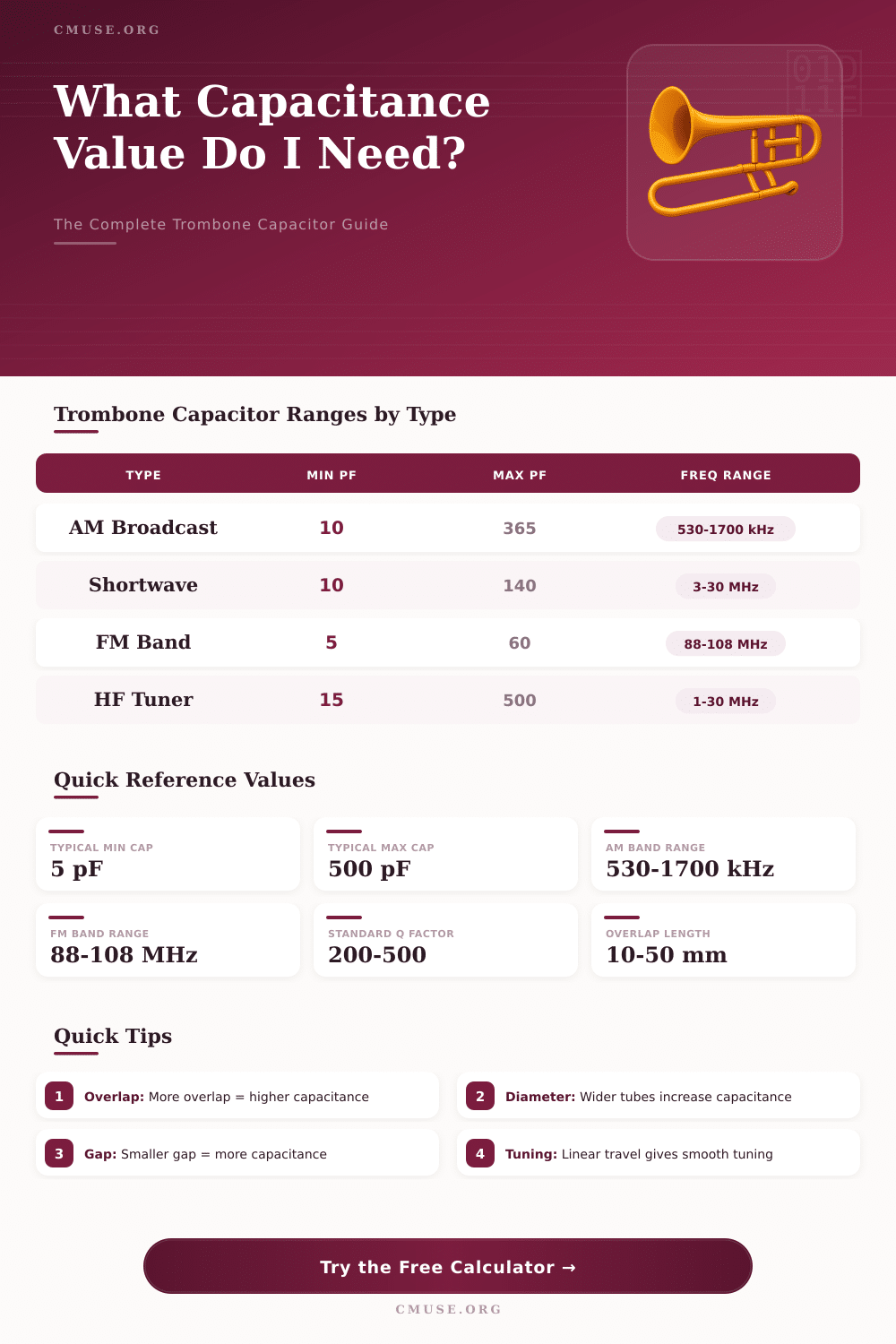
| AM Broadcast Tuner | 30 | 28 | 5–50 | 10–365 |
| Shortwave Receiver | 20 | 18.5 | 3–30 | 10–140 |
| FM Band Tuner | 15 | 14 | 2–20 | 5–60 |
| HF Antenna Coupler | 40 | 38 | 5–70 | 15–500 |
| VHF Preamp | 10 | 9 | 1–15 | 2–30 |
| Transmitter Tank | 50 | 48 | 10–100 | 50–800 |
The trombone capacitor works similarly to its namesake, it is made up of one tube that slips in another to alter the capacitance value. It became very liked between folks that build little magnetic antennas, chiefly because those antennas require a variable capacitor that will not break under high voltage. The design of the trombone capacitor handles that quite effectively.
The principle of its working is quite simple. One takes two tubes with a bit different diameters and puts one in the other, with insulating layer between them. When the internal tube slips inside or outside, the overlapping surfaces move, and that genuinely alters the capacitance value.
How a Trombone Capacitor Works and How to Make One
One sample that I found uses 14 mm copper tube, that slips in 16 mm tube from plastic-aluminum-plastic. The antenna itself forms one plate, while the sliding tubes act as the sceond.
Build such capacitor does not require rocket science and folks commonly become creative during the process. Some start with two aluminum plates. Others choose more unusual ways, for instance, one uses cans, where one slips in the other after stretching with a tool for exhaust tubes.
I even observed designs with household cans, in witch one bottles the content and wraps it with membrane. One builder showed a genuinely original idea, taking aluminum tube and Red Bull tin with almost 5.2 mm space between them, later using foam to set everything in the device.
Also copper tube appears in various designs. One folk combined eight bits of it end to end. Other builder originally planned to do a fixed capacitor from sheet for operation on 40 m, but ultimately chose trombone capacitor style from copper tube.
The insulating material between the tubes matters more than one could believe. Teflon works well as dielectric. There is a design with tube that has internal layer from PTFE, aluminum in the centre and yellow plastic on the outside.
Thanks to that PTFE layer, 19 mm copper tube works for trombone capacitor.
Here are the main limits of trombone capacitors, they are not perfect. The coaxial form is less efficient than designs with several layers stacked parallel with short heavy connections. That same problem that makes spiral coils wasteful, one finds also in trombone capacitors.
I heard of builders that trombone capacitors do not tune like paperbutterly capacitors.
When one hardly finds ready variable capacitors, building a trombone capacitor at home becomes a practical choice. There are visual guides for the building process, especially for little magnetic antennas. The designs of trombone capacitor and butterfly capacitor commonly appear together in discussions (it is useful to compare both), if you decide whatmore suits yourproject for a magnetic device.