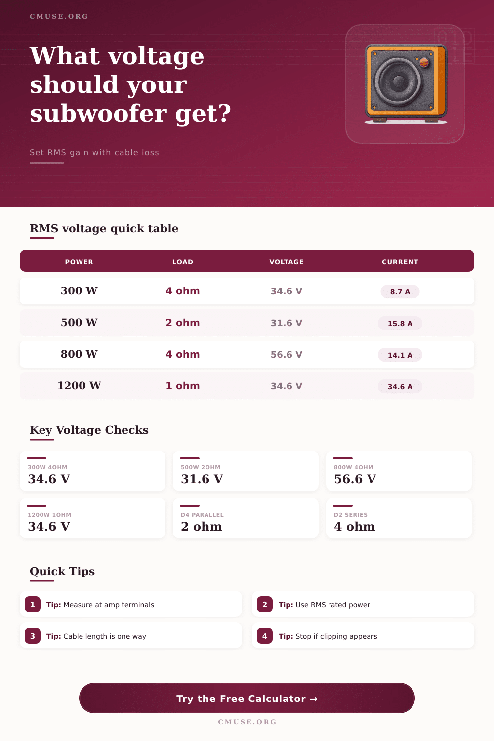
Subwoofer Voltage Calculator
Calculate RMS speaker-terminal voltage, current, cable drop, and amplifier demand for gain setting and subwoofer load checks.
🔊 Quick Presets
⚙ Subwoofer Voltage Inputs
📊 Load Spec Comparison Grid
📈 RMS Voltage Reference Table
| Target Power | 1 Ohm Load | 2 Ohm Load | 4 Ohm Load | 8 Ohm Load |
|---|---|---|---|---|
| 100 watts RMS | 10.0 V, 10.0 A | 14.1 V, 7.1 A | 20.0 V, 5.0 A | 28.3 V, 3.5 A |
| 250 watts RMS | 15.8 V, 15.8 A | 22.4 V, 11.2 A | 31.6 V, 7.9 A | 44.7 V, 5.6 A |
| 500 watts RMS | 22.4 V, 22.4 A | 31.6 V, 15.8 A | 44.7 V, 11.2 A | 63.2 V, 7.9 A |
| 750 watts RMS | 27.4 V, 27.4 A | 38.7 V, 19.4 A | 54.8 V, 13.7 A | 77.5 V, 9.7 A |
| 1000 watts RMS | 31.6 V, 31.6 A | 44.7 V, 22.4 A | 63.2 V, 15.8 A | 89.4 V, 11.2 A |
| 1500 watts RMS | 38.7 V, 38.7 A | 54.8 V, 27.4 A | 77.5 V, 19.4 A | 109.5 V, 13.7 A |
🔀 Voice Coil Wiring Reference
| Driver / Coil Set | Parallel Result | Series Result | Common Amp Match |
|---|---|---|---|
| Single 2 ohm subwoofer | 2 ohms | 2 ohms | Mono amps rated at 2 ohms |
| Single 4 ohm subwoofer | 4 ohms | 4 ohms | Home, plate, and bridged amps |
| Dual 4 ohm voice coils | 2 ohms | 8 ohms | 2 ohm mono or 8 ohm hi-fi use |
| Dual 2 ohm voice coils | 1 ohm | 4 ohms | 1 ohm mono or 4 ohm stability |
| Two single 4 ohm subs | 2 ohms total | 8 ohms total | Shared mono amp channel |
| Four 4 ohm coils | 1 ohm all parallel | 4 ohms series-parallel | High-current mono amp systems |
🔌 Speaker Cable Drop Reference
| Copper Gauge | Resistance per 1000 ft | 20 ft Round Trip Drop at 15 A | Best Use |
|---|---|---|---|
| 18 AWG | 6.385 ohms | 1.92 V | Short, lower-power runs only |
| 16 AWG | 4.016 ohms | 1.20 V | Moderate home subwoofer runs |
| 14 AWG | 2.525 ohms | 0.76 V | General subwoofer cable choice |
| 12 AWG | 1.588 ohms | 0.48 V | Longer or higher-power runs |
| 10 AWG | 0.999 ohms | 0.30 V | High-power car and PA subs |
| 8 AWG | 0.628 ohms | 0.19 V | Very high-current short links |
🎚 Test Tone and Headroom Reference
| Setting | Voltage Factor | Power Factor | Meaning For Gain Setup |
|---|---|---|---|
| 0 dB test tone | 1.000x | 1.000x | Conservative full-scale sine reference |
| -3 dB test tone | 0.708x | 0.501x | Meter reads lower for the same gain |
| -5 dB test tone | 0.562x | 0.316x | Common for subwoofer music headroom |
| -10 dB test tone | 0.316x | 0.100x | Large crest allowance; watch clipping |
| +1 dB voltage margin | 1.122x | 1.259x | Requires about 26% more amplifier power |
| +3 dB voltage margin | 1.413x | 1.995x | Nearly doubles amplifier power demand |
🎛 Amplifier Platform Comparison
| Platform | Typical Efficiency Used | Supply Voltage Used | Calculator Role |
|---|---|---|---|
| Class D car amplifier | 82% | 14.4 V DC | Estimates alternator and power-wire current |
| Class AB car amplifier | 62% | 14.4 V DC | Shows higher input current for same speaker watts |
| Class D plate amplifier | 86% | 120 V AC | Approximates wall input current for home subs |
| Class AB home amplifier | 58% | 120 V AC | Useful for older linear amplifier estimates |
| Class D pro amplifier | 88% | 120 V AC | PA and rehearsal room subwoofer planning |
Setting a subwoofer gain is a mathematic process and not a matter of guessing. Many people treats the gain knob on a subwoofer as a volume control. However, the subwoofer gain knob are actualy used to control the voltage that is sent to the subwoofer.
If the gain knob is adjusted too high, the amplifier can begin to clipping the signal that is being sent to the subwoofer. Clipping the signal can lead to damage to the voice coil of the subwoofer. The goal is to find the voltage that will allow the amplifier to deliver the rated RMS power to the subwoofer without clipping the signal.
How to Set Your Subwoofer Gain
To achieve this goal, it is first important to understands the relationship between power, impedance, and voltage. These three concept are related through the science of electrical physics. The power that an amplifier delivers to a subwoofer is related to the voltage of that signal and the impedance of the subwoofer.
Impedance is related to the wattage that the amplifier delivers to the subwoofer. For subwoofers with a one ohm load, the wattage will be higher then subwoofers with a four ohm load. The impedance of a subwoofer can change depending on how the voice coils are wired.
If the voice coils are wired in parallel, the impedance will decreases. However, if the voice coils are wired in series, the impedance will increase. Due to the ability of impedance to change, the target voltage for the subwoofer gain can also change.
Many people use a digital multimeter to measure the voltage of the signal that is being sent to the subwoofer. However, the digital multimeter will read the voltage of the signal only if the signal being measured is the correct type of test signal. The most common test signal is a zero decibel sine wave.
However, some people use a minus five decibel sine wave instead. Using the minus five decibel signal will make the digital multimeter read less voltage than if a zero decibel sine wave was being used. Thus, the type of sine wave used will change the voltage that the digital multimeter measures and thus affect the calculation of the target voltage for the subwoofer gain.
The resistance of the cables that are used to connect the amplifier to the subwoofer can also play a factor in the voltage that reaches the subwoofer. Speaker wire isnt made of materials with zero resistance. Each foot of speaker wire will add to the resistance of the system.
This resistance will cause the voltage to drop from the amplifier to the subwoofer. Using long speaker wires or thin gauge speaker wires will increase the resistance and the voltage drop. Using thicker gauge speaker wires will increase the voltage that reaches the subwoofer.
Another factor to consider is the efficiency of the amplifier. For instance, class D amplifiers are more efficient than class AB amplifiers. When an amplifier sends power to a device like a subwoofer, the amplifier must draw more power from the power supply than the subwoofer use.
Thus, if an amplifier draws a large amount of power, the lights in the vehicle may dim as the amplifier is drawing that much power from the power supply. One other concept that could of been used when setting the gain on a subwoofer is the concept of headroom. Headroom relate to the ability of the amplifier to provide additional power to the subwoofer over the rated RMS power of the subwoofer.
Some people want to set the gain so the amplifier provides exactly the rated RMS power to the subwoofer. Others want to provide headroom so that the amplifier can provide additional power to the subwoofer when needed. Providing headroom will increase the voltage that the amplifier demands from the power supply.
Thus, people who desire subwoofers with headroom must balance the desire for the amplifier to deliver the maximum power to the subwoofer with the reliability of the amplifier. If an amplifier is push too hard, it could fail. Finally, understanding the relationship between power, impedance, voltage, and cable resistance allow an individual to correctly set the gain on a subwoofer in a way that ensures that the subwoofer is not damaged.