Subwoofer Impedance Calculator
Combine voice coils, multiple subs, amp load limits, and wiring resistance to estimate the final impedance your amplifier will see.
🔊 Wiring Presets
🎛 Impedance Inputs
📊 Subwoofer Wiring Spec Comparison Grid
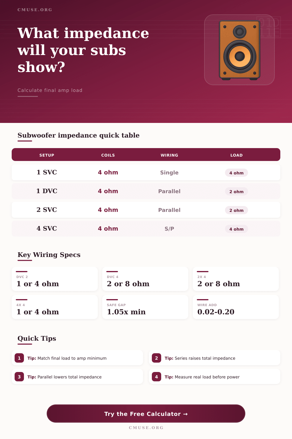
Voice Coil Wiring Outcomes
| Subwoofer Type | Coil Rating | Wiring Inside Sub | Per-Sub Load |
|---|---|---|---|
| Single voice coil | 4 Ω | Single coil path | 4 Ω |
| Dual voice coil | 2 Ω + 2 Ω | Series coils | 4 Ω |
| Dual voice coil | 4 Ω + 4 Ω | Parallel coils | 2 Ω |
| Quad voice coil | 4 Ω each | Series-parallel coils | 4 Ω |
Equal Subwoofer Array Reference
| Array | Each Sub Load | Parallel Total | Series Total |
|---|---|---|---|
| 1 subwoofer | 4 Ω | 4 Ω | 4 Ω |
| 2 subwoofers | 4 Ω | 2 Ω | 8 Ω |
| 3 subwoofers | 4 Ω | 1.33 Ω | 12 Ω |
| 4 subwoofers | 4 Ω | 1 Ω | 16 Ω |
Amplifier Minimum Load Check
| Calculated Load | 2 Ω Stable Amp | 1 Ω Stable Amp | Typical Status |
|---|---|---|---|
| 4.00 Ω | Safe margin | Safe margin | Cooler, lower output |
| 2.00 Ω | At rating | Safe margin | Common mono load |
| 1.00 Ω | Below rating | At rating | Needs 1 Ω amp |
| 0.50 Ω | Below rating | Below rating | Competition only |
Copper Speaker Wire Resistance Allowance
| Wire Gauge | Approx Resistance | 10 ft Round Trip | 20 ft Round Trip |
|---|---|---|---|
| 12 AWG copper | 1.59 Ω / 1000 ft | 0.016 Ω | 0.032 Ω |
| 14 AWG copper | 2.53 Ω / 1000 ft | 0.025 Ω | 0.051 Ω |
| 16 AWG copper | 4.02 Ω / 1000 ft | 0.040 Ω | 0.080 Ω |
| 18 AWG copper | 6.39 Ω / 1000 ft | 0.064 Ω | 0.128 Ω |
Impedance is the resistance that the amplifier must overcome in order to move the cones of the subwoofer. If the impedance of the subwoofers is too low for the amplifier, the amplifier will attempt to deliver too much electrical currents to the subwoofer. The result of attempting to deliver too much current to an amplifier may result in the amplifier overheating, clipping, or cease to function altogether.
It is necessary for the impedance of the subwoofers to be matched with the impedance capability of the amplifier, as matching these two values will ensure the safety of the amplifier and the subwoofers themselfs. Subwoofers often use components called voice coil. Voice coils can be of a single design or of a dual design.
How to Match Subwoofer and Amplifier Impedance
A dual voice coil subwoofer contain two voice coils within the subwoofer’s frame. The benefit of this dual voice coil design is that altering how the voice coils are wired to one another can change the impedance of the subwoofer. Wiring the voice coils in series will add the resistance of each voice coil together, increasing the total impedance.
Wiring the voice coils in parallel will allow the electrical current to split between the two coil, decreasing the total impedance. Thus, the ability to wire the coils in either series or parallel allow the user to adjust the impedance of the subwoofer to match that of the amplifier. When adding more than one subwoofer to a car stereo system, the total impedance of the system will change.
Adding additional subwoofers will either increase or decrease the impedance of the system. Many car audio system designer choose to wire the subwoofers in parallel with one another in order to lower the impedance of the system. Lower impedance allow the amplifier to produce more power.
However, you should take care not to wire the subwoofers in parallel if the calculated impedance will be lower then the minimum impedance that the amplifier can handle. For instance, attempting to run a 2-ohm stable amplifier at a 1-ohm load will damage the amplifier. The resistance of the copper wire that connects the amplifier to the subwoofers should also be considered when setting up the audio system.
In a laboratory setting, a scientist will calculate the resistance of the subwoofers alone. However, within a vehicle, the copper wire have its own resistance. More specifically, the electricity has to travel through several foot of copper wire.
Thus, the copper wire will add a small amount of resistance to the system. The impedance of the subwoofers can be calculated in such a way that the resistance of the copper wire is also considered. In this scenario, the resistance of the copper wire will provide a small safety buffer for the amplifier.
When measuring the impedance of a subwoofer, a multimeter will read the DC resistance of the speaker. The DC resistance will be lower than the nominal impedance of the subwoofer. Subwoofers are dynamic electrical loads, and their impedance change with the frequency of the sound that it is playing and the temperature of the speakers voice coils.
The nominal impedance is the average impedance of the speaker, while the actual impedance can change while the speaker is in operation. Thus, a reference table can be used to determine the difference between the nominal impedance and the actual impedance of subwoofers. In addition to low impedance, there are other reasons to wire a system of subwoofers in a way that create a high impedance for the amplifier.
An amplifier that is operating at a higher impedance will be running at a lower temperature. An amplifier that runs at a lower temperature will produce a more cleaner signal. Thus, another consideration for designing an audio system is whether the audio system will prioritize the volume of sound that is created by the system or the reliability of the amplifier.
If reliability is the priority, a margin of safety should of be provided for the amplifier, meaning that the impedance of the subwoofers should be higher than the absolute minimum safe impedance of the amplifier. Finally, these considerations should be thought out prior to install the subwoofers into the vehicle.