Series Pickup Resistance Calculator
Estimate guitar pickup series DC resistance, loaded output, resonance, and brightness risk from pickup DCR, inductance, coil mode, pots, amp input, and cable capacitance.
Load a real guitar or bass wiring scenario, then adjust the pickup measurements. Series pickup wiring adds DC resistance directly, while pots, amp input, and cable capacitance decide how much high end survives.
Series Pickup Resistance Breakdown
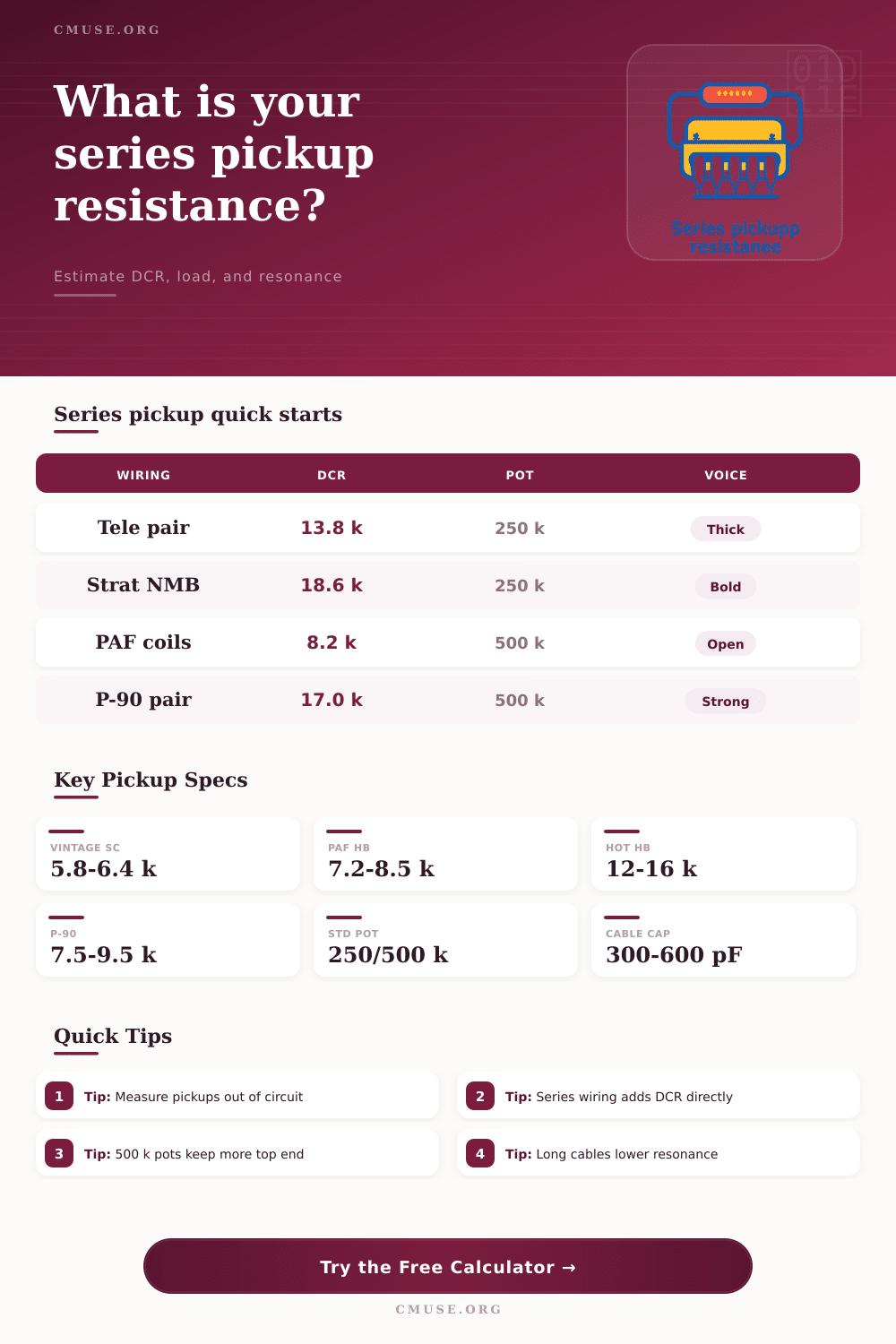
Rseries = (RA + RB + RC) x turnFactor + RaddedRload = 1 / (1/Rvol + 1/Rtone + 1/Ramp)Vout = Rload / (Rseries + Rload)f0 = 1 / (2 x pi x sqrt(Lseries x Ctotal))Vintage Strat-style single coil DCR
PAF-style humbucker total DCR
Hot humbucker DCR region
Common P-90 pickup DCR
Typical single-coil volume pot value
Typical humbucker volume pot value
Common guitar cable capacitance range
Common passive guitar pickup inductance
| Pickup Type | Typical DCR Range | Typical Inductance | Series Calculator Note |
|---|---|---|---|
| Vintage Strat-style single coil | 5.6 to 6.6 kOhm | 2.0 to 3.2 H | Three in series can exceed 18 kOhm and move the resonant peak downward. |
| Tele neck and bridge pair | 6.0 to 8.2 kOhm each | 2.0 to 4.0 H each | Series switching gives a thicker voice than the normal parallel middle position. |
| PAF-style humbucker coil pair | 3.6 to 4.3 kOhm per coil | 1.8 to 2.7 H per coil | The two coils already form the classic series humbucker baseline. |
| Hot ceramic humbucker | 6.0 to 8.0 kOhm per coil | 3.0 to 5.5 H per coil | High DCR and high inductance can sound dark with 250 kOhm loading. |
| P-90 pickup pair in series | 7.5 to 9.5 kOhm each | 4.0 to 6.5 H each | Use 500 kOhm pots or a shorter cable if the resonance gets too low. |
| Jazz Bass pickup pair | 7.0 to 8.8 kOhm each | 3.0 to 4.8 H each | Series wiring raises output and midrange while reducing glassy treble. |
| Wiring Choice | Resistance Rule | Expected Result | Useful Check |
|---|---|---|---|
| Two pickups in series | Add pickup A and pickup C DCR. | More output, stronger mids, and lower resonant frequency than parallel wiring. | Compare calculated DCR to a meter reading at the output jack. |
| Three pickups in series | Add neck, middle, and bridge DCR. | Very strong midrange with a larger treble drop from inductance and cable capacitance. | Use no-load tone or 500 kOhm pots if the result is too dark. |
| Humbucker coil pair | Add both coils; ignore the middle slot. | Normal full humbucker operation with hum cancellation when coils are opposite magnetic polarity. | Coil split roughly halves DCR and greatly reduces inductance. |
| Bass split-coil series | Add both split halves or both pickups. | Classic thick bass voice with strong fundamental and quieter single-coil noise. | Check that phase and polarity are correct before judging the resistance. |
| Partial split resistor | Add the resistor path only when it sits directly in series. | Can keep some body while lowering one coil's contribution. | Measure the actual switch position because wiring layouts vary. |
| Load Setup | Effective Load Trend | Resonance Effect | Calculator Starting Point |
|---|---|---|---|
| 250 kOhm volume and 250 kOhm tone | Heavy passive loading | Damps the resonant peak and smooths bright single coils. | Use 250 for both pot inputs and 1 MOhm amp input. |
| 500 kOhm volume and 500 kOhm tone | Lighter passive loading | Keeps more peak height and treble in humbuckers and series mods. | Use 500 for both pot inputs when testing a brighter series voice. |
| No-load tone control at full | Reduced tone-pot loading | Raises apparent brightness without changing pickup DCR. | Enter 1000 kOhm or higher for tone pot loading. |
| Short low-capacitance cable | Lower capacitance | Raises resonant frequency, often making series wiring clearer. | Use 200 to 350 pF for cable capacitance. |
| Long vintage-style cable | Higher capacitance | Lowers resonance and can make hot series wiring sound rounded. | Use 600 to 900 pF for cable capacitance. |
| Scenario | Starting Inputs | Primary Result To Watch | Typical Reading |
|---|---|---|---|
| Tele 4-way switch series position | 6.3 kOhm neck, 7.5 kOhm bridge, 250 kOhm pots | Total DCR and loaded output ratio. | About 13 to 15 kOhm before pot loading. |
| Strat all-three series experiment | Three 6.0 to 6.4 kOhm pickups with 250 kOhm pots | Resonance and loaded Q. | Often strong but noticeably darker than normal Strat combinations. |
| PAF humbucker rebuild check | Two 4.0 kOhm coils with 500 kOhm pots | Coil balance and resonance. | Around 8 kOhm total with a moderate resonant peak. |
| Hot humbucker into 250 kOhm controls | Two 7.0 kOhm coils and higher inductance | Output loss and low resonance warning. | Can read powerful but dark unless load is lightened. |
| Jazz Bass series switch | Two 7.5 to 8.5 kOhm pickups with 250 kOhm pots | Series DCR and cable capacitance. | Strong midrange with less open top than parallel wiring. |
While most of us spend time thinking about gauge and magnet selection for pickups, we don’t often consider what occurs once the signal pass them. A vintage-correct wound coil doesn’t matter much if you run it to an amp via a cable that sucks high frequencies or use incorrect pot values. Series wired pickups makes all this even more complicated because each additional coil provide increased output while also significantly increasing the inductance and capacitance drag. Knowing how these elements relate is difference between a clear articulate rhythm sound and a muddy mess that will bury itself in the mix.
The calculator above will do the math for you: How does your chosen combination of pots, coils and cables interact to change color of final signal? It does more than just show total DC resistance (which indicates how much electrical load the circuit put on the pickups). It also predicts resonant peak, which is where the pickup’s own inductance meets capacitance of the cable(s) and produces a naturaly boost of some frequencies over others.
How Series Wiring Changes Your Sound
Wire pickups in series, and you’re stacking up their resistances while adding together their inductances. Parallel-wired Telecaster neck and bridge sound twangy and bright; switch ’em into series and they has a thick, almost humbucker-like voice. The physics is simple enough: The more coils, the bigger the voltage potential, but it also means there’s a heavier electrical inertia created, rolling off the top end unless compensated for elsewhere in the circuit.
The other thing to remember is that DC resistance isn’t everything. It won’t tell you what your guitar will sound like underneath your fingertips. That’s where inductance comes in, the tool calculate this from your measured resistance and number of coil turns. Single coils has airiness thanks to their low inductance, whereas high output humbuckers is punchy and compressed due to higher inductance. If you want something weird, you can wire three pickups in series. Well, the inductance has tripled so it’s pulling resonant peak lower into the mids. Unless you short your cable or fiddle around with your volume pot, lowering amount of capacitance, you’re going to end up with a dark dull tone.
This is laid out on the page as a reference table showing how various pickup types react to these loads so you can understand why a vintage PAF needs 500k pots while a hot ceramic rail might choke with them.
Another common error among modders is assuming more resistance means louder volume. Yes, it will increase volume at first. However, if the combined impedance of your amp and all other pedals in your chain are higher than input impedance of your amplifier, you’ll start experiencing passive loading and will therefore lose signal strength. The calculator displays this as a percentage so you can actualy visualize the exact amount of voltage loss occurring prior to reaching your amplifier. So when you see this number getting too low, it may be time to switch out for a bigger pot value or move to a buffered pedal. It’s not a race to find largest numbers; it’s about maintaining enough signal quality in order to retain the character of the pickup.
One thing we tend to overlook when calculating inductors and capacitors are the effects of cable length. If you use a really long coiled cable, you’ll find all of that capacitance kills any high end clarity you may have had completely. Because of the increased inductance in the series wiring, the capacitor’s effects becomes even stronger. That short little patch cable might sound awesome on stage, but switch over to a twenty-foot cable while recording and it just won’t have the same bite anymore. With the ability to adjust the input for cable capacitance, the tool allows you to see what the translation will be between the practice room and studio before you go.
The bottom line is that series wiring is a game of balance: what do you want for output? What do you want retained in terms of frequencies? Remember, the entire idea behind adding coils are to trade brightness for power. Now understanding how those three elements; capacitance, inductance, and resistance. Interact turns your guesswork into engineering your sound. From modifying a vintage guitar to building a new bass, when you know why your rig sounds as it does, you make deliberate decisions instead of fortunate ones. You should of checked everything twice. And that same insight gained by testing out your pickups can be applied to the entire signal chain so that the voice you hear at home is the voice the audience hears on stage.