🔊 RMS to Peak-to-Peak Calculator
Convert between RMS, Peak, and Peak-to-Peak voltage values for any waveform type
(RMS/Peak)
(Peak/RMS)
(RMS = Peak)
(RMS/Peak)
(RMS/Peak)
(RMS/Peak)
(always 2 × Peak)
(= 1.41421)
| Signal Level | dBu / dBV | RMS Voltage | Peak Voltage | Peak-to-Peak |
|---|---|---|---|---|
| 0 dBu Reference | 0 dBu | 0.7746 V | 1.095 V | 2.190 V |
| Pro Line Level | +4 dBu | 1.228 V | 1.736 V | 3.472 V |
| Consumer Line Level | -10 dBV | 0.316 V | 0.447 V | 0.894 V |
| 0 dBV Reference | 0 dBV | 1.000 V | 1.414 V | 2.828 V |
| EIA Standard | -8 dBu | 0.308 V | 0.436 V | 0.872 V |
| Mic Level (typical) | -52 dBu | 0.00245 V | 0.00346 V | 0.00693 V |
| Phono MM Output | ~-55 dBu | 0.0014 V | 0.00198 V | 0.00396 V |
| CD Player Output | +6 dBu | 1.549 V | 2.190 V | 4.380 V |
| DAT / Digital Output | +18 dBu | 6.162 V | 8.714 V | 17.43 V |
| Eurorack CV (±5V) | n/a | 3.536 V | 5.000 V | 10.00 V |
| Peak Voltage | Sine RMS | Square RMS | Triangle RMS | Peak-to-Peak |
|---|---|---|---|---|
| 0.5 V | 0.354 V | 0.500 V | 0.289 V | 1.000 V |
| 1.0 V | 0.707 V | 1.000 V | 0.577 V | 2.000 V |
| 1.414 V | 1.000 V | 1.414 V | 0.816 V | 2.828 V |
| 2.0 V | 1.414 V | 2.000 V | 1.155 V | 4.000 V |
| 5.0 V | 3.536 V | 5.000 V | 2.887 V | 10.00 V |
| 10 V | 7.071 V | 10.00 V | 5.774 V | 20.00 V |
| 20 V | 14.14 V | 20.00 V | 11.55 V | 40.00 V |
| 50 V | 35.36 V | 50.00 V | 28.87 V | 100.0 V |
| RMS Voltage | Power @ 4Ω | Power @ 8Ω | Power @ 16Ω | Peak Voltage |
|---|---|---|---|---|
| 1 V RMS | 0.25 W | 0.125 W | 0.063 W | 1.414 V |
| 2.828 V RMS | 2 W | 1 W | 0.5 W | 4.000 V |
| 4 V RMS | 4 W | 2 W | 1 W | 5.657 V |
| 8.944 V RMS | 20 W | 10 W | 5 W | 12.65 V |
| 17.89 V RMS | 80 W | 40 W | 20 W | 25.30 V |
| 28.28 V RMS | 200 W | 100 W | 50 W | 40.00 V |
| 40 V RMS | 400 W | 200 W | 100 W | 56.57 V |
| 56.57 V RMS | 800 W | 400 W | 200 W | 80.00 V |
Root Mean Square (RMS) voltage and peak-to-peak (Vpp) voltage is two different ways to measure voltage in electronic circuits. Understanding the difference between RMS voltage and peak-to-peak voltage are necessary to effectively troubleshoot electronic circuits. RMS voltage indicate the heating equivalent of the signal.
In other words, RMS voltage indicates an average power that a resistor would experience if the signal was held constant. However, this does not tell you the maximum voltage of a signal, so peak-to-peak voltage is used to measure this. Peak-to-peak voltage is important in understanding amplifier and DACs, as peak-to-peak voltage can tell you if a DAC or amplifier is clipping.
What is RMS and Peak-to-Peak Voltage
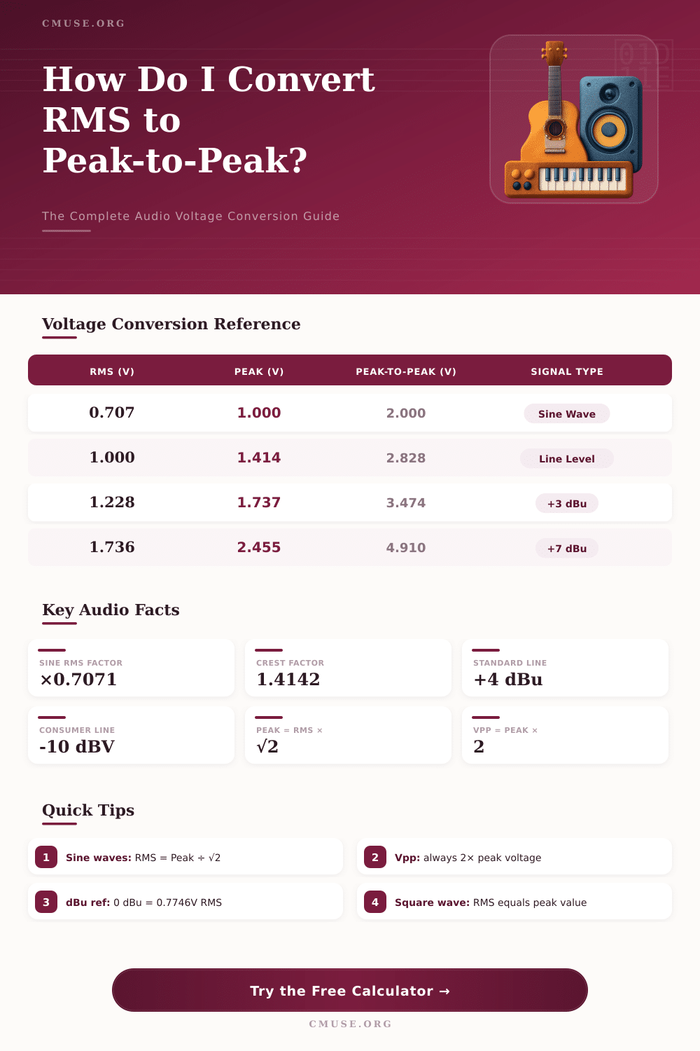
The formula for converting RMS voltage to peak-to-peak voltage depend on the type of waveform that is being measured. For a sine wave, you multiply the RMS voltage by approximately 2.8 to find the peak-to-peak voltage. For a square wave, you multiply the RMS voltage by 2 to find the peak-to-peak voltage.
For a triangle wave, the RMS voltage is multiplied by 3.5 to find the peak-to-peak voltage. The crest factor is the ratio of the peak voltage to the RMS voltage. This is a number that expresses how much energy is contained in the peaks of a signal.
If only the RMS voltage was measured, the peak-to-peak voltage would not be understood. Therefore, you must also measure the peak-to-peak voltage. In many professional audio environments, different voltage references are used.
For example, professional recording studios use a line level signal of 0.775 Vrms, also known as 0 dBu. If the signal is a sine wave at 0.775 Vrms, the peak-to-peak voltage would be approximately 2.2 Vpp. If the signal is +4 dBu, which is 1.2 Vrms, then the peak-to-peak voltage is 3.5 Vpp.
Consumer audio gear often utilize -10 dBV. At -10 dBV, the signal is 0.3 Vrms. The peak-to-peak voltage for this signal is less than 1 Vpp.
These voltage levels are used so that audio gear of different types can communicate with one another without damaging the audio gear. Another important factor is the load resistance of the circuit. The load resistance impact the voltage and the power of a circuit.
Power can only be calculated with the load resistance of a circuit. Furthermore, to find the voltage of a circuit, you must also use the load resistance. For instance, if there is a 25-watt headphone amplifier driving a 32-ohm load, the peak-to-peak voltage is 28 Vpp for a sine wave signal.
For an 8-ohm speaker load, the voltage and current create significant power. In this case, you must monitor the waveform of the signal to ensure it does not exceed the power limits of the speaker. Another factor that can impact the voltage of a signal is the presence of a DC offset.
For circuits that are powered by a single power supply, the DC offset can shift the maximum and minimum voltage levels of a signal. This offset can be problematic in these types of circuits. The crest factor can be adjusted for different types of signals with an oscilloscope.
For instance, signals like soft-clipped audio or generator frequency sweeps are not mathematically represented as a sine wave. The crest factor for these types of signals will be lower than 1.4. You can manually adjust the crest factor on an oscilloscope to take into account the nature of the signal being measured.
By adjusting the crest factor, any mathematical calculations made with the signal will match the actual signal being measured. Another common of confusion in audio and electronic circuits is decibel (dB) references. The dBV reference assumes that 1 Vrms is used as the zero point.
However, the dBu reference assumes that 0.775 Vrms is the zero point. These scale are logarithmic scales used to represent voltage levels. In order to calculate any value of voltage from the decibel reading, you must convert the decibel value into voltage levels.
For instance, +4 dBu is 1.2 Vrms into a 600-ohm load at 1 mW. To ensure accurate measurements of electronic circuits, there are a few different tools that can be used. To measure RMS voltage, you should use a true-RMS meter.
Cheap AC meters will not provide the more accurate measurements of RMS voltage. To observe crest factor, an oscilloscope should be used. If you are measuring audio signals, the crest factor should be adjusted for music signals, as music with many drums will exhibit a high crest factor.
The efficiency of the amplifier and impedance of headphones should also be considered. The impedance of headphones can impact the voltage and current in headphones. Common mistake when measuring voltage include ignoring the load resistance of circuits and assuming that the signal is a sine wave.
If you dont consider the load resistance, then the RMS voltage measurements will be inaccurate. If the current is measured without knowing the load resistance, the voltage stress on the circuit will not be understood. In addition to these common mistakes, it is also important to remember that not all signals are a sine wave.
The voltage of clipped guitar signals or the voltage of a square wave from a synthesizer will have a different relationship between the RMS voltage and the peak-to-peak voltage. By following these steps, electrical troubleshooting will be made easier. For instance, clipping on an audio circuit indicates that the peak-to-peak voltage of a signal is at least 10% to 20% higher than the power supply rails.
If there is a shortage of headroom in the circuit, you should increase the crest factor. For electrical circuits, it is best to use RMS voltage as a baseline measurement for power. However, to see the full voltage swing that a circuit demands from a power supply, the peak-to-peak voltage should be used.