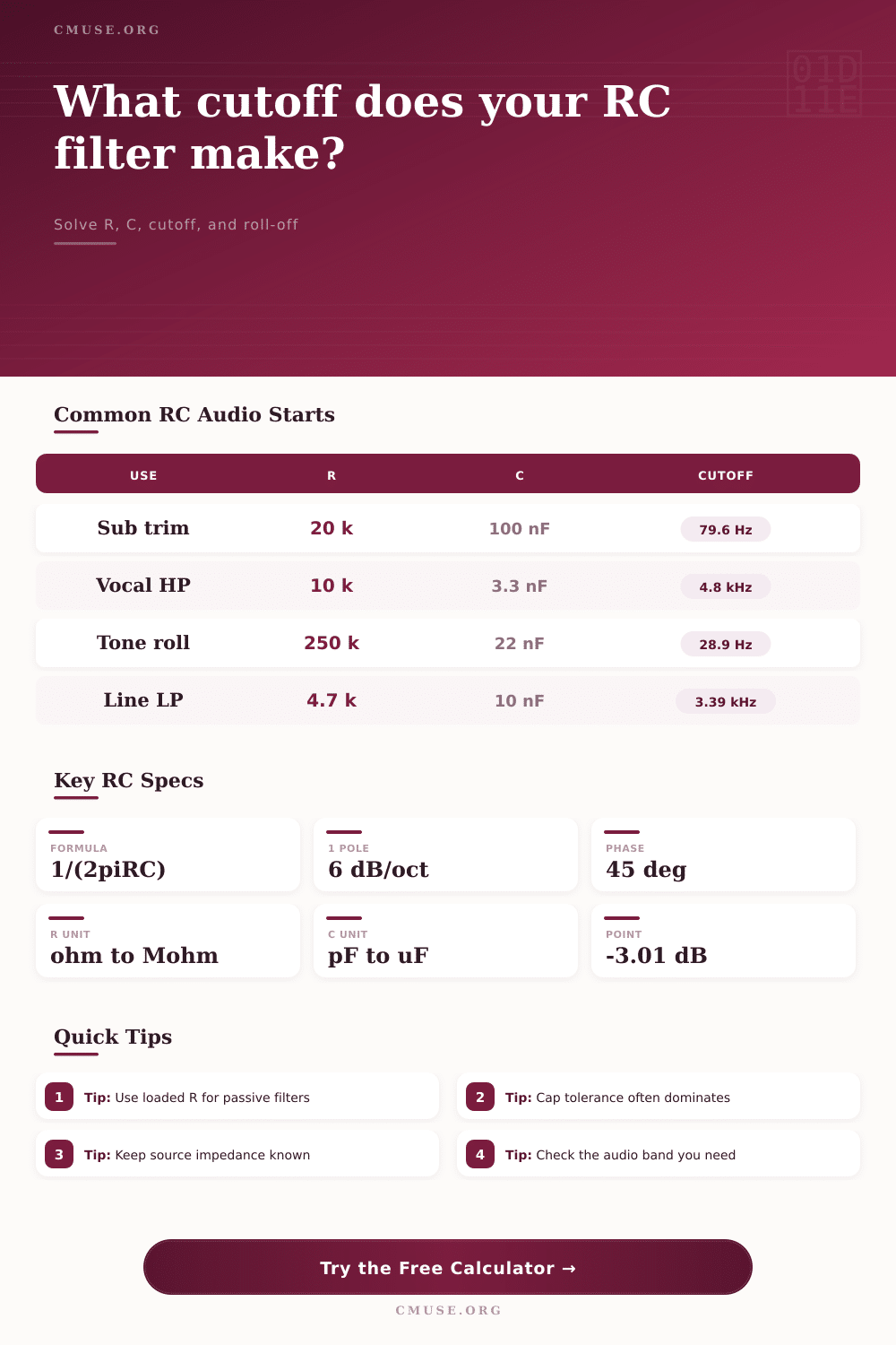
Filter Cutoff From RC Calculator
Convert resistor and capacitor values into RC filter cutoff, solve the missing part, estimate loaded passive poles, tolerance spread, phase, and audio-band attenuation.
🎯 RC Filter Presets
⚙ Resistor, Capacitor, Cutoff Inputs
📊 Current RC Snapshot
🎛 Audio Filter Comparison Grid
Treble trim or anti-click smoothing
One resistor and one capacitor make a gentle 6 dB per octave roll-off. Loading changes the pole, so use the calculator with real source and load values.
Coupling cap or rumble cleanup
A series capacitor and resistance define the low-frequency corner. It is common at pedal, preamp, mixer, and line-input boundaries.
Buffered RC before gain or op amp
A buffer protects the RC value from the next input. The cutoff stays closer to 1 / (2 pi RC) and the response is easier to repeat.
More attenuation, rounded transition
Matched first-order stages add slope, but their combined -3 dB point shifts. Use the stage count here for passband and stopband estimates.
📐 Resistor, Capacitor, And Cutoff Tables
| Resistor | Best RC Use | With 10 nF | With 100 nF | Audio Note |
|---|---|---|---|---|
| 1 kΩ | Low impedance buffer output | 15.92 kHz | 1.59 kHz | Small loading risk after an op amp |
| 2.2 kΩ | Pedal output smoothing | 7.23 kHz | 723 Hz | Good for bright edge control |
| 4.7 kΩ | Mixer or synth line stage | 3.39 kHz | 339 Hz | Common value with stable film caps |
| 10 kΩ | General line-level RC | 1.59 kHz | 159 Hz | Usually friendly to modern inputs |
| 22 kΩ | Gentle high-pass or low-pass | 723 Hz | 72.3 Hz | Watch noise in high-gain circuits |
| 47 kΩ | Guitar and instrument networks | 339 Hz | 33.9 Hz | Loading becomes musically obvious |
| 100 kΩ | High impedance tone shaping | 159 Hz | 15.9 Hz | Leakage and tolerance matter more |
| 250 kΩ | Passive guitar pot region | 63.7 Hz | 6.37 Hz | Pickup interaction dominates tone |
| Capacitor | Common Label | With 10 kΩ | With 47 kΩ | Practical Audio Use |
|---|---|---|---|---|
| 100 pF | 101 | 159 kHz | 33.9 kHz | RF bleed and ultrasonic trimming |
| 470 pF | 471 | 33.9 kHz | 7.20 kHz | Cable and pickup brightness shifts |
| 1 nF | 102 | 15.9 kHz | 3.39 kHz | Top-end softening |
| 3.3 nF | 332 | 4.82 kHz | 1.03 kHz | Presence-band contour |
| 10 nF | 103 | 1.59 kHz | 339 Hz | Midrange low-pass color |
| 22 nF | 223 | 723 Hz | 154 Hz | Guitar tone-cap classic value |
| 47 nF | 473 | 339 Hz | 72.1 Hz | Warm passive instrument roll-off |
| 100 nF | 104 | 159 Hz | 33.9 Hz | Rumble, envelope, and control smoothing |
| Target Cutoff | Capacitor | Needed Resistor | Resistor Family | Audio Placement |
|---|---|---|---|---|
| 20 Hz | 100 nF | 79.6 kΩ | 82 kΩ | Subsonic high-pass coupling |
| 80 Hz | 100 nF | 19.9 kΩ | 20 kΩ | Sub crossover check point |
| 160 Hz | 47 nF | 21.2 kΩ | 22 kΩ | Bass cleanup or warm low-pass |
| 500 Hz | 10 nF | 31.8 kΩ | 33 kΩ | Mid filter transition |
| 1 kHz | 10 nF | 15.9 kΩ | 16 kΩ | Voice and pedal tone shaping |
| 4 kHz | 10 nF | 3.98 kΩ | 3.9 kΩ | Lo-fi and brightness control |
| 8 kHz | 2.2 nF | 9.04 kΩ | 9.1 kΩ | Sibilance or presence trimming |
| 16 kHz | 1 nF | 9.95 kΩ | 10 kΩ | Ultrasonic or RF-adjacent roll-off |
| Frequency Ratio | Low-Pass Loss | High-Pass Loss | Phase Size | One-Pole Meaning |
|---|---|---|---|---|
| 0.25 x cutoff | -0.26 dB | -12.30 dB | 14.0 deg | Low-pass nearly flat, high-pass still rejecting |
| 0.5 x cutoff | -0.97 dB | -6.99 dB | 26.6 deg | Gentle bend before the corner |
| 1 x cutoff | -3.01 dB | -3.01 dB | 45.0 deg | Standard RC cutoff definition |
| 2 x cutoff | -6.99 dB | -0.97 dB | 26.6 deg | One octave past cutoff |
| 4 x cutoff | -12.30 dB | -0.26 dB | 14.0 deg | Two octaves past cutoff |
💡 RC Filter Tips
There’s a certain type of quiet panic that sets in when you construct an audio circuit and discover that it has no effect on tone. You check your capacitor and resistor; everything look right on breadboard. But when you sweep the frequency, there is a drop point that doesn’t make any sense for how you designed this thing. Most likely, you’ve fallen victim to not considering what plugs into the other end of wire.
The equation for cutoff frequency is pretty simple in textbook but often fails in real circuit. For example, it assume a perfect, unloaded situation where only the capacitor and resistor interact with each other. They’re not alone in real world. You can let the calculator do the math for you (above), but the point of knowing why it tweaks the math is that it helps you design.
Why Real Circuits Are Different From Theory
By choosing a loaded passive model, you’re already conceding that the next stage in your signal chain want to pull a certain amount of current, and it has an opinion about how much. So you put your filter resistor in series, but that input impedance is now in parallel. If you don’t account for it, your cutoff changes. Driving a fifty kilohm input with a twenty kilohm resistor doesn’t make a twenty kilohm RC time constant. The effective resistance go down and the cutoff increases. You get a brighter tone then intended. It’s a subtle thing, but when you’re aiming to reduce a harsh treble peak or clean up some rumble from a live recording, it makes all the difference.
The other silent killer in precise filter design is capacitor tolerance. We buy metal film resistors easily now; they has a one percent tolerance. They are treated like an exact value. Cheap ceramic capacitors is a wild card. Film caps typicaly have a ten percent tolerance. So when coupled with a five percent resistor the worst case spread of your cutoff frequency can widen enough to shift a vocal filter from helpful to destructive.
By showing you the range, the tool takes this into account. Not only will it tell you where the pole is, it will tell you where it may wander if your parts bin isn’t carefully sorted. Most designers look at the center frequency and forget the edges. Look at the edges.
The nature of the filter also varies as you add more stages stacked on top of one another. One pole yields six decibels of attenuation per octave. That’s gentle and allows sound to pass through with a soft knee. Two poles (the same pole cascaded) means steeper attenuation. But now each load the other so the -3dB point moves down. You can estimate this with calculator. What you see is it isn’t simply a matter of throwing in a few more components to build a steeper filter. It becomes an exercise in keeping tabs on how those components interact, yes you gain slope but you give up some passband predictability.
The page has a reference table. This is for typical values, so you don’t have to do the math in your head during soldering time. It connects the theoretical to the practical. Ten nanofarads at ten kilohms comes out around a kilo-and-a-half hertz. That’s a good mental starting point for shaping midrange frequencies. However, keep in mind that these are ballpark numbers; they’re meant as guidelines but not absolute.
Capacitor values will be affected by temperature. Old pots may get some humidity inside them over time and your DMM has an error range. So at the end of the day, building an RC filter isn’t about being able to hit some frequency with exact accuracy as much as it’s about knowing how the components you select will affect your circuit.
Big capacitors is expensive, big capacitors use up space. Low resistance values mean high current draw, but they also mean picking up noise. How do you balance those physical limitations with the electrical? That’s where the tool comes in. It does the algebra for you, freeing you up to think about the engineering side of things.
It gives you a starting point. From there you listen, measure, iterate. Learn what your circuit actualy does, rather than just what the equations say it should of do. That difference between theory and practice is where good audio design lives.
Remember to keep the source impedance known. Know which audio band you want. And make sure the load isn’t ruining all that hard work.