Ratio to dB Calculator
Convert amplitude, voltage, sound pressure, power, intensity, or perceived loudness ratios into decibel changes, final levels, and equivalent ratio families.
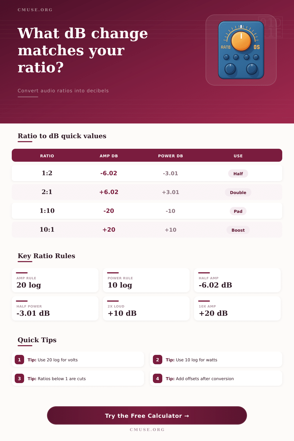
| Ratio | Amplitude / Pressure dB | Power / Intensity dB | Typical Audio Meaning |
|---|---|---|---|
| 1:100 | -40.00 dB | -20.00 dB | Very large attenuation or noise drop. |
| 1:10 | -20.00 dB | -10.00 dB | Common pad, noise, or level reduction check. |
| 1:2 | -6.02 dB | -3.01 dB | Half voltage or half power reference. |
| 1:1 | 0.00 dB | 0.00 dB | Unity ratio, no level change. |
| 2:1 | +6.02 dB | +3.01 dB | Double voltage or double power reference. |
| 10:1 | +20.00 dB | +10.00 dB | Ten times amplitude or ten times power. |
| 100:1 | +40.00 dB | +20.00 dB | Large gain or dynamic range ratio. |
| Ratio Family | Formula | Use For | Interpretation |
|---|---|---|---|
| Amplitude / voltage | 20 log10(output / reference) | Samples, line voltage, plugin gain, fader ratios | Ratio of signal amplitude. |
| Sound pressure | 20 log10(pressure / reference) | SPL pressure ratios and microphone pressure | Pressure amplitude ratio. |
| Power / intensity | 10 log10(power / reference) | Watts, acoustic intensity, amplifier power | Energy or power ratio. |
| Perceived loudness | 10 log2(loudness multiplier) | Rough listening comparisons | 2x loudness is about +10 dB. |
| Scenario | Ratio Basis | Ratio | dB Result |
|---|---|---|---|
| Half a voltage or sample amplitude | Amplitude | 1:2 | -6.02 dB |
| Double an amplifier power value | Power | 2:1 | +3.01 dB |
| Reduce noise intensity to one tenth | Power | 1:10 | -10.00 dB |
| Apply a ten-to-one voltage pad | Amplitude | 1:10 | -20.00 dB |
| Double listener distance in free field | Pressure | 1:2 | -6.02 dB |
| Estimate twice perceived loudness | Loudness | 2:1 | +10.00 dB |
| Percent of Reference | Amplitude dB | Power dB | Practical Meaning |
|---|---|---|---|
| 10% | -20.00 dB | -10.00 dB | Strong voltage pad or one tenth power. |
| 25% | -12.04 dB | -6.02 dB | Quarter amplitude or quarter power. |
| 50% | -6.02 dB | -3.01 dB | Half amplitude or half power. |
| 100% | 0.00 dB | 0.00 dB | Unity reference. |
| 200% | +6.02 dB | +3.01 dB | Double amplitude or double power. |
| 400% | +12.04 dB | +6.02 dB | Four times amplitude or four times power. |
Decibels are used to describe the ratio of changes in a signals amplitude or power. Raw measurements of voltage and wattage is difficult for many peoples to use because of the linear changes in the values of those measurement. Using decibels allows engineers to more easily describe the change of sound with a scale that is easier to use than raw voltage or wattage measurement.
Decibels can show the ratio of voltage changes, or the ratio of power change. Since decibels use a logarithmic scale, it can easily show very large changes or very small changes in relation to the original measurement. The formula for calculating decibels change based on whether the measurement of the signal is of the amplitude of the signal or the power of the signal.
Decibels and How to Use the Calculator
If an engineer is measuring the signal for amplitude or sound pressure, twenty multiplies the logarithm of the ratio. If the signal is being measured for power, ten multiplies the logarithm of the ratio. Power is related to the amplitude of a signal through the formula that state that power is related to the square of the amplitude of that signal.
If the voltage of a signal is doubled, the power of that signal will quadruple. Because of this different relationship between power and amplitude, different formula are used to describe the changes in each of those measurements. These ratio can be encountered in a variety of ways by engineers.
Two common ways that engineers use these ratios are in the adjustment of gain on a device, or in the use of a pad to reduce the voltage of a signal. If a pad is used to reduce the voltage of a signal by half, the voltage will drop by six decibels. Using the same pad will also reduce the power of the signal by half, but the decibel value of that change is different than that of the voltage change.
This calculator provide both measurements to help engineers understand the effect that one measurement has on the signal and its power. Another way that distance create ratios is in relation to sound pressure. If a signal is traveling in a free space, the sound pressure will decrease with the square of the distance from the source of the sound.
If an engineer walks twice as far away from the sound source, the sound pressure will be halved. If the sound pressure is halved, the amplitude of the signal is represented by a ratio of one-to-two, which translate to a change in decibel value of six decibels. This ratio of distance and sound pressure can be used by engineers to determine the amount of power that an amplifier should have to ensure that the sound reach the audience at a certain distance.
Using these ratios, engineers can use the calculator to test different scenario in their engineering work. Another way that engineers experience ratios is through the perception of loudness. The human ear perceives the loudness of a sound to double when the loudness of a signal is increased by ten decibels.
This rule of thumb are an average, and the loudness of a signal may not increase by precisely ten decibels to be perceived as twice as loud. For instance, if a signal is compressed to reduce the peaks of the signal by six decibels, the signal will be quieter, but it will not be half as loud. The loudness mode on the calculator use the approximation of loudness that the human ear perceives to allow engineers to set a desired loudness level for a signal and set the number of decibels that must be applied to the signal for that loudness to be achieved.
Some of the most common mistake that engineers make with decibels are due to the incorrect use of units or the incorrect application of the formula. For instance, an engineer may measure the voltage level of a signal, yet use the formula for power. This error will introduce any mistake in calculating the signal.
The decibel calculator described in this article include built in safety measures to prevent these common errors. Based on the type of signal that an engineer is measuring, the calculator will prompt the engineer to select the correct basis for the signal measurement. The calculator will adjust the number that is to be entered into the offset field to ensure that it reflect the calculated value of the signal.
The offset fields are used to reflect the starting point of the signal. For instance, a microphone may start at a sound pressure level of seventy-four decibels. When a decibel pad and gain are added to the signal, the level will change.
The offset fields will show the effect of the additions on the signal, but the pads own offset field will represent the effect of the pad. This field is important for engineers to see the effect of the ratio that is being calculate in relation to the signal that is being measured. Tables of the most common ratio can be found on the calculator as memory aids for engineers.
For instance, one table may display the ratio of voltage to decibels for a ten-to-one ratio in voltage; such a ratio is equal to twenty decibels. However, the ratio of power to decibels for the same signal will be ten decibels. These tables allow engineers to avoid making mistakes using incorrect assumptions about the relationship between ratios and decibels.
The decibel calculator will also calculate the equivalent ratios in the opposite direction. For instance, if voltage is to be cut by six decibels, the signal will have a quarter-power reduction. This reverse calculation ensure that engineers understand the impact of changes in both decibels and watts to the signal being measured.