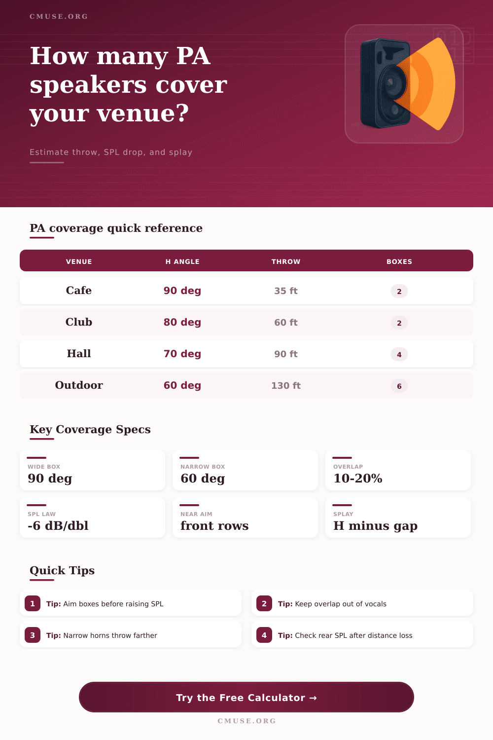
PA Speaker Coverage Calculator
Estimate horizontal and vertical coverage, throw distance loss, audience width, overlap, splay angle, rear SPL, and the number of PA boxes needed for a venue.
Load a named venue shape, then tune the dispersion angles, audience size, overlap, SPL target, and box limit to match the actual rig.
90 deg
Horizontal horn angle
60 deg
Vertical horn angle
-18 dB
Distance loss to rear
10%
Horizontal overlap target
| Nominal Pattern | Best Use | Coverage Character | Planning Note |
|---|---|---|---|
| 100 x 60 deg | Small rooms and short throws | Very wide horizontal spread | Can hit side walls quickly |
| 90 x 50 deg | General portable PA | Balanced width and control | Common two-box starting point |
| 75 x 40 deg | Medium halls and clubs | Tighter mid-room control | Needs more precise aiming |
| 60 x 40 deg | Long throws and outdoor lanes | Narrower, more directed energy | Often needs more boxes for width |
| 40 x 20 deg | Long-throw array elements | Highly controlled coverage | Used in multi-box arrays |
| Venue Preset | Audience Width | Rear Throw | Starting Pattern |
|---|---|---|---|
| Coffeehouse Duo | 28 ft / 8.5 m | 35 ft / 10.7 m | 100 x 60 deg compact tops |
| Small Worship Room | 52 ft / 15.8 m | 55 ft / 16.8 m | 90 x 50 deg point source |
| Live Music Club | 70 ft / 21.3 m | 65 ft / 19.8 m | 80 x 50 deg mains |
| Hotel Ballroom | 95 ft / 29.0 m | 85 ft / 25.9 m | 75 x 40 deg mains plus fills |
| Outdoor Festival | 160 ft / 48.8 m | 140 ft / 42.7 m | 60 x 40 deg array zones |
| Distance From Box | Free-Field Loss | Meaning For PA | Coverage Check |
|---|---|---|---|
| 3.3 ft / 1 m | 0 dB reference | Most SPL ratings start here | Too close for audience estimates |
| 10 ft / 3 m | About -9.2 dB | Front-row level can be high | Check vertical aim and fills |
| 33 ft / 10 m | About -20 dB | Useful small-room throw | Wide boxes often cover enough |
| 66 ft / 20 m | About -26 dB | Typical club rear loss | Rear SPL and width both matter |
| 132 ft / 40 m | About -32 dB | Outdoor or long-room loss | Consider arrays or delay fills |
| Overlap Target | Approx Splay | Use Case | Watch Point |
|---|---|---|---|
| 0 percent | Equal to horizontal angle | Hard left/right separation | Can leave a seam between boxes |
| 10 percent | 90 percent of horn angle | Portable PA starting point | Good balance of width and blend |
| 15 percent | 85 percent of horn angle | Vocal-heavy rooms | Watch comb filtering near center |
| 20 percent | 80 percent of horn angle | Distributed or fill zones | Can build excess level overlap |
| 25 percent | 75 percent of horn angle | Dense coverage smoothing | Needs careful equalization |
| System Shape | Typical Boxes | Coverage Role | Planning Cue |
|---|---|---|---|
| Stereo point-source mains | 2 boxes | Small to medium rooms | Works when each side covers half the room |
| Mains plus front fills | 4 boxes | Wide front rows | Fills cover seats below main horn aim |
| Horizontal array per side | 4 to 6 boxes | Wide rooms and ballrooms | Splay keeps overlap controlled |
| Line array or column zones | 6 to 12 boxes | Longer throws with vertical control | Vertical coverage drives trim and angle |
| Delay-supported long room | 4 plus delays | Rear SPL recovery | Delay speakers reduce front system strain |
A sound engineer has to plan how the sound from the speakers will reach the audience. A sound engineer must consider many different variable in this planning process. The distance between the stage and the back wall of the performance space is one variable.
However, the angle of the speaker horns and the height of the speaker boxes are also variables for sound engineers to consider. If a sound engineer dont consider these variables, the sound may be too loud for the front rows of the audience but not loud enough for the back rows of the audience. A coverage calculator can help a sound engineer to account for these variables because it can calculate the complex mathematics involve in calculating sound coverage.
How to plan speaker coverage
The sound engineer can begin to calculate the sound coverage for a performance space by considering the horn pattern of the speaker systems. Horn patterns can be found on the speaker data sheet for the speakers. Horn patterns determine how the sound from the speakers spreads across a specific width at a specific distance from the speakers.
For example, if a speaker has a 90-degree horizontal horn angle, the sound will spread across a specific width at that distance. If the sound engineer doubles the distance from the speaker to where the audience’s ears are located, the sound will also double in the number of degree of width that the sound spreads. By entering the distance that the sound will travel (the throw distance) and the width of the audience into the coverage calculator, the sound engineer can determine how many speaker boxes will be required to cover the audience.
Furthermore, the sound engineer can also enter the desired percentage of overlap between speaker coverage in the coverage calculator. The percentage of overlap that is chosen will affect the number of speaker boxes that the coverage calculator recommends. For instance, a ten percent overlap between speakers creates a small amount of space between the speaker boxes; a twenty percent overlap will create a smoother transition in the sound between speaker boxes because the twenty percent overlap requires the use of more speaker cabinets to accomplish the desired smooth transition in sound.
Another variable that the sound engineer must consider is the vertical coverage. For instance, the speakers may be very loud at the required sound pressure levels for the audience; however, the speaker may not have proper vertical coverage to reach each listener. The height of the acoustic center of the speaker array and the height of the audience ears are two measurement that can help to determine the down-tilt angle of the speakers that will be used in the venue.
Furthermore, an acoustic system that is designed to provide sufficient sound for the front rows of audience members may not have enough vertical span to provide sufficient sound to the audience members sitting in the back rows. If the vertical sound pattern of the speakers cannot cover the vertical span of the audience, front fills or a second sound zone may be required. The coverage calculator software can display this information for the sound engineer to review.
Another consideration of sound pressure levels is the loss of sound that occurs with distance between the speakers and the audience’s ears. Sound pressure level (SPL) levels naturaly diminish with distance from the speakers due to the inverse square law in free field conditions. Furthermore, although the SPL calculations are a mathematically determined value, the sound that is measured in a real room may be different due to the reflections of sound waves off of the walls or the absorption of sound energy by those walls.
The SPL calculations can be adjusted for outdoor sound field environments using the “room support” adjustment on the coverage calculator. Furthermore, multiple speaker boxes will produce coupling gain that can overcome some of the loss of SPL that occurs with distance between the speakers and the audience. Another setting within the coverage calculator is the percentage of overlap between speakers.
The software can calculate the splay angle between the speaker boxes based off the overlap percentage that is selected by the sound engineer. Furthermore, the angle that the software recommends for the splay angle between speaker boxes is just a starting point for the installation of the speaker system. The sound engineer should use a microphone to measure the sound in the performance space with the speakers aimed at the audience.
The actual SPL of the sound that is reflected off of the performance space walls may not equal the SPL that the software calculated. New speaker system installers often make some common mistakes during the speaker system installation process. One of the most common is aiming the speaker horn boxes at the audience; however, the coverage angle is actualy a nominal angle and is not the maximum angle of the speakers.
Another of the most common mistakes is aiming the vertical sound pattern of the speaker system at the ears of the audience members in the back rows of the audience; if the speaker is aimed only at the back rows of audience members, the sound pressure levels will be high for the audience members in the front rows. A third of the most common installation mistakes is ignoring the number of speaker boxes that the sound engineer owns. The coverage calculator will show how many speaker boxes would be required to provide the SPL levels that are needed for each audience member in the venue; however, the sound engineer cannot purchase more speaker boxes than he or she owns.
Thus, the sound engineer must enter the maximum number of speaker boxes that he or she owns in the software; if the number of speaker boxes that is required for the coverage calculator is higher than the maximum number of speaker boxes that is entered, the software will alert the sound engineer to that possibility. The reference tables that are included in the coverage calculator page provide information about the size of typical performance venues and the horn angles for speakers that are typically used in those performance spaces. These tables are not rules; however, using these tables can reduce the number of variable that the sound engineer must consider for each installation job.
For instance, a coffeehouse may not use the same horn angles as a sound system that is used at a music festival. Furthermore, the sound engineer can use the preset buttons on the coverage calculator to determine the impact that a change in settings will have upon the number of speaker boxes that will be used for the venue and the SPL of the speakers at the rear rows of the audience. Outdoor speaker system installations may include considerations of the effects of the wind and the humidity in the area where the speakers will be installed.
The effects of the wind and the humidity have more of an effect upon the high frequencies of sound that the speakers project than upon the low frequencies of sound. Furthermore, the coverage calculator cannot calculate the effect of the wind upon the sound that is projected by the speakers; however, it can calculate the sound loss that would occur in an outdoor area in the absence of wind. For indoor speaker systems, the sound reflections off of the side walls and the low ceilings in those venues can become a problem.
Furthermore, the SPL that is entered into the coverage calculator should be that of the sound of the type of program material that will be played in the venue; speech will have different SPL requirements than a full band playing rock music. The SPL that is programmed into the software indicates the difference between sound pressure levels that are within the comfort range of the audience members and those that may make the audience members uncomfortable. The goal of the coverage calculator is not to use the software to calculate the sound pressure levels such that the SPL hits the exact number that is required for audience members.
Rather, the goal of the coverage calculator is to allow the sound engineer to understand the trade-offs between SPL, number of speaker boxes, and distance that are required for even coverage of all audience members. For instance, if the coverage calculator determines that the number of speaker boxes that are required to achieve even SPL levels throughout the audience is more than the sound engineer owns, there are trade-offs that can be made. For instance, the sound engineer could choose to use delay fills to even out the SPL at the audience members in the rear rows; he or she could also buy speaker boxes with narrower horn angles to reduce the SPL requirements; or the sound engineer could raise the target SPL requirements for the audience members in the back rows.
Each of these trade-offs can be seen before the sound engineer begins installing the speaker system into the performance venue.