Negative Feedback Ratio Calculator
Estimate feedback divider beta, output transformer tap scaling, closed-loop voltage gain, loop gain, and gain reduction for audio amplifier feedback networks.
| Common network | Series resistor | Return resistor | Divider beta | Ideal gain |
|---|---|---|---|---|
| Blackface-style guitar amp return | 820 ohm | 47 ohm tail injection | 5.41% | 18.5x |
| Marshall-style presence network base | 47 k ohm | 5 k ohm presence path | 9.62% | 10.4x |
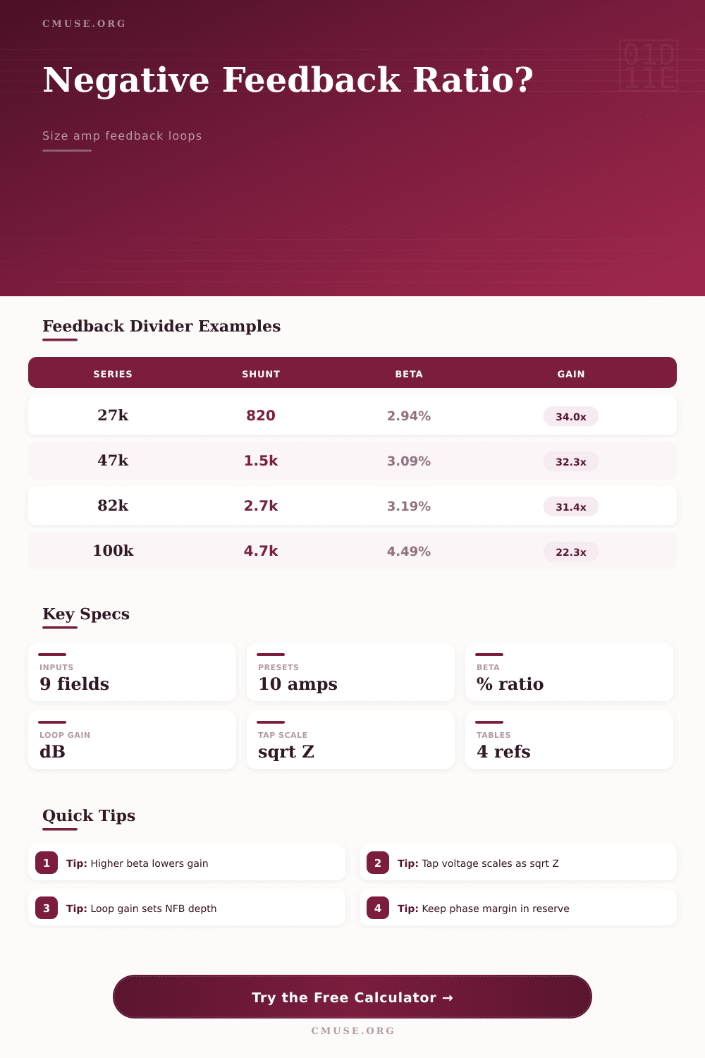
| Hi-fi moderate feedback divider | 27 k ohm | 820 ohm | 2.94% | 34.0x |
| High-gain tube power amp sample | 82 k ohm | 2.7 k ohm | 3.19% | 31.4x |
| Deep solid-state voltage feedback | 22 k ohm | 1 k ohm | 4.35% | 23.0x |
| Feedback tap | Reference tap | Voltage scale | Feedback change | Rule used |
|---|---|---|---|---|
| 4 ohm | 8 ohm | 0.707 | -3.01 dB | sqrt(4 / 8) |
| 8 ohm | 8 ohm | 1.000 | 0.00 dB | sqrt(8 / 8) |
| 16 ohm | 8 ohm | 1.414 | +3.01 dB | sqrt(16 / 8) |
| 2 ohm | 8 ohm | 0.500 | -6.02 dB | sqrt(2 / 8) |
| Aol beta | Loop gain dB | Gain reduction | Closed-loop accuracy | Typical feel |
|---|---|---|---|---|
| 1 | 0.0 dB | 6.0 dB | Loose, far from 1 / beta | Light control |
| 3 | 9.5 dB | 12.0 dB | Moderate accuracy | Vintage control |
| 10 | 20.0 dB | 20.8 dB | Close to 1 / beta | Firm damping |
| 30 | 29.5 dB | 29.8 dB | Very close | Hi-fi control |
| 100 | 40.0 dB | 40.1 dB | Nearly exact | Very tight |
| Topology | Usual global NFB depth | Return point | Design note | Calculator cue |
|---|---|---|---|---|
| Long-tail pair tube power amp | 6 to 20 dB | Phase inverter tail | Classic guitar and hi-fi output feedback. | Use real tail impedance. |
| Cathodyne inverter amp | 3 to 12 dB | Preamp cathode or driver | Less spare loop gain than LTP layouts. | Watch phase margin. |
| Single-ended tube amp | 0 to 10 dB | Input or cathode return | Transformer phase shift can limit depth. | Keep beta modest. |
| Ultralinear hi-fi tube amp | 12 to 26 dB | Differential input or cathode | Screen taps add local feedback before global NFB. | Measure Aol with loop open. |
| Discrete solid-state power amp | 20 to 50 dB | Differential input pair | Large gain bandwidth can support deeper loops. | Check unity loop crossing. |
| Op-amp based power stage | 40 to 80 dB at low frequency | Inverting input network | Open-loop gain falls rapidly with frequency. | Use Aol at test frequency. |
This is the transition from math to real-world applications in amplifier design. For example, you can theoreticaly calculate a feedback loop that will decrease your distortion by 10-fold amount. But when it’s applied acousticaly, perhaps speaker have become harsh sounding or even begin oscillating at high frequencies. That’s where the negative feedback ratio calculator come into play.
It connects dots between what a gain reduction ought to be and what those components is actualy doing. It accounts for acoustic effects like phase shifts, transformer windings, and other component tolerances. Those are variable that gets swept under rug of textbooks to maintain clarity with the equations.
How to Balance Math and Sound in Amp Design
Negative feedback is pretty straight-forward: Take some fraction of output signal, invert that signal’s phase, and feed that back to cancel out any error. More feedback mean less distortion and a flatter frequency response. Once you know those two numbers (open-loop gain & divider value), the calculator figure out the rest for you. No need to derive beta by hand each time you change resistor.
Now, it is important to know what it measure. It tell you exactly how much amp will correct itself. But it also tells you just how unstable it will become if anything should of go wrong downstream.
Another variable are easy to overlook. Your output transformer has a feedback tap point, which can make a big difference if you are using the eight ohm tap and then driving a four ohm load. In this case, the voltage relationship change dramatically. The tool takes care of this as well, and scales the feedback factor based off the square root of the impedance ratio.
There’s a hidden error in your gain calculation. A mismatch at this point make it so you might think you’ve got twenty decibels of loop gain when in fact you don’t have nearly that much. This means there is more distortion then expected. These are small details, but they is very important if you want accuracy.
Compare your old guitar amp to your new hi-fi monitor. One will typically use small amounts of feedback to maintain harmonic richness; the other require steep loops for clinical clarity. You’ll see that spectrum reflected in the calculator’s presets. They demonstrate how a Blackface-type circuit functions different than, say, a discrete solid-state stage.
A tube amp based on a long-tail pair design typically use moderate depth of feedback returned to its phase inverter tail. By comparison, an op-amp power stage may hide distortions beneath forty decibels of gain reduction. Neither is right or wrong but each must be approached very differently to maintain stability.
Secondly, know where you’re pushing the loop gain limit. More isn’t always better; there are diminishing returns when you push the beta too far with insufficient open-loop gain. While the calculator makes clear what your closed-loop gain and reduction will be, it can’t measure the stray capacitance on your breadboard or the leakage inductance of whatever transformer you use.
These parasitic factor add phase lag which reduce your margin for error. Increasing the depth of feedback may well lead to oscillation if your estimated phase margin are low. Stability isn’t all about gain, it’s also about timing and it work for a reason.
There is a tendency among many designer to assume that feedback solves all problems with poorly designed front-ends. While feedback can hide distortion and other noise artifacts, it do not solve basic topology errors. For example, the high source impedance at the summing node will affect the effective return resistance. This, in turn, modify the beta value across frequencies.
This is what the reference tables on the page illustrate: how typical networks behave given normal conditions. These are more like a sanity check than hard-and-fast rules.
In the end, it’s all about compromising on a feedback ratio. Too little and there will be no control of output impedance and distortion. Too much and you risk a dull tone as well as stability issues. Your ears make the call; the numbers point the way.
Dialing it in right means that what was a circuit becomes an instrument, one that you feel more than hear. At this point, the math is over and music begins. And we’re back at that original instant when calculation give way to perception.