Modulation Bandwidth Calculator
Estimate occupied bandwidth, significant sidebands, channel fit, and Nyquist headroom for FM synthesis, AM, ring modulation, vibrato, tremolo, and broadcast-style modulation.
🎧 Modulation Presets
🎛 Modulation Inputs
📊 Core Modulation Specs
🔎 Spec Comparison Grid
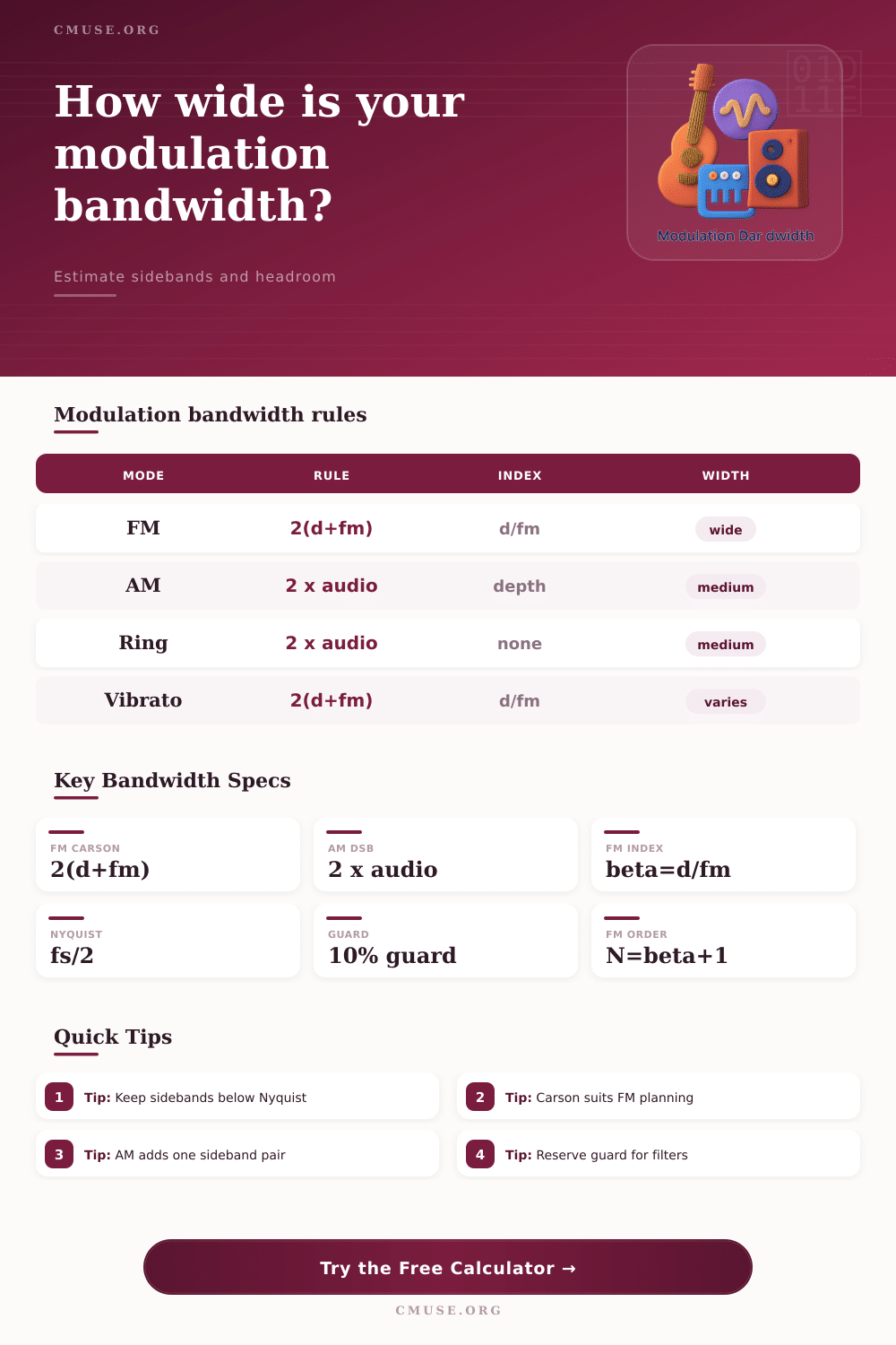
| Modulation Mode | Primary Formula | Sideband Pattern | Best Use |
|---|---|---|---|
| FM / Vibrato | Bandwidth = 2 x (peak deviation + highest modulating frequency) | Carrier plus paired sidebands at n x modulator frequency | Pitch modulation, FM synthesis, RF FM planning |
| PM | Equivalent FM bandwidth can be estimated from measured peak deviation | Similar paired sidebands when translated to frequency deviation | Phase-mod synth patches and digital oscillator phase input |
| AM / Tremolo | Bandwidth = 2 x highest modulating frequency | Carrier plus upper and lower sidebands for each modulator component | Level modulation, tremolo, envelope-shaped carrier studies |
| Ring Mod | Bandwidth = 2 x highest modulating frequency around the carrier | Sum and difference products; carrier is ideally suppressed | Metallic effects, frequency shifting studies, sideband design |
| FM Index Beta | Common Description | Approx. Sideband Order | Bandwidth Behavior |
|---|---|---|---|
| 0.1 to 0.5 | Narrow modulation; vibrato or subtle FM color | 1 to 2 pairs | Bandwidth stays close to carrier and modulator frequency |
| 1 to 2 | Moderate FM; clear extra partials | 2 to 3 pairs | Carson and sideband estimates begin to widen |
| 3 to 5 | Bright FM tone; strong upper and lower products | 4 to 6 pairs | Useful audio range can grow several times the modulator rate |
| 6 and above | Very wide FM; dense sideband cluster | 7 or more pairs | Check Nyquist and channel width before committing settings |
| Sample Rate | Nyquist Limit | Practical Audio Note | Modulation Check |
|---|---|---|---|
| 44,100 Hz | 22,050 Hz | Common music delivery rate | Keep highest generated sideband below 22.05 kHz |
| 48,000 Hz | 24,000 Hz | Common video and studio session rate | Useful for most LFO and moderate audio-rate modulation |
| 96,000 Hz | 48,000 Hz | High-rate sound design and analysis | Gives extra room for wide FM before aliasing |
| 192,000 Hz | 96,000 Hz | Specialized capture or measurement rate | Useful when extreme sideband spans must be inspected |
| Scenario | Typical Inputs | Expected Bandwidth | Secondary Spec |
|---|---|---|---|
| Vocal vibrato | 5 to 7 Hz LFO, 3 to 8 Hz deviation | About 16 to 30 Hz by Carson rule | Beta often near 0.5 to 1.5 |
| Guitar tremolo | 4 to 10 Hz LFO, 40 to 90 percent depth | About 8 to 20 Hz double-sideband spread | Carrier tone remains unless fully gated |
| FM synth bell | Hundreds of Hz modulator, beta 2 to 5 | Several kHz of generated partial spread | Sideband order often 3 to 6 pairs |
| Broadcast FM max | 75 kHz deviation, 15 kHz audio | About 180 kHz by Carson rule | Fits common 200 kHz spacing with guard planning |
When you use modulation to shape a sounds, the modulation causes the sound’s energy to spread away from the starting frequency of the carrier wave. This spreading of energy form sidebands around the carrier frequency, and the sidebands determine how much of the frequency spectrum the modulated sound claim for itself. If the sidebands take up too much of the frequency spectrum, the sound may create aliasing.
Thus, sound engineer must understand how much of the frequency spectrum an modulated signal claims before they determine whether or not the rest of the signal chain can process the signal. Frequency modulation create very wide footprints in the frequency spectrum because the carrier frequency itself modulates. If the frequency and deviation of the modulator are low, the footprint of the frequency modulation will be modest.
How Modulation Makes a Sound Use More Frequencies
However, if the frequency and deviation of the modulator are high, the modulator pushes the partials of the modulated sound well beyond its original pitch. Carson’s rule for frequency modulation estimates where most of the energy of the FM sound will be located in the frequency spectrum. Carson’s rule add the peak deviation of the modulator from the carrier frequency to the highest frequency of the modulating signal and then multiplies that sum by two.
This calculation determine whether the tone will fit within a filter or whether it will move into the next octave. Phase modulation creates a signal that has the same characteristics as FM modulation. Thus, FM and PM modulation have the same planning steps, with the frequency deviation of the FM modulator replacing the depth of the phase modulator.
Amplitude modulation, tremolo, and ring modulation have a completely different and much simpler rule for setting the width of the modulated sound in the frequency spectrum. For both amplitude modulation and tremolo, each component of the modulating signal create one frequency component above the carrier frequency and one below the carrier frequency. Thus, the width of the sound is twice the bandwidth of the modulating signal.
For ring modulation, the same rule apply to the sum and difference products of the ring modulator. The ring modulator removes the dry carrier frequency in the ideal case; hence, the same amount of headroom is required for the ring modulator as for either amplitude or tremolo modulation. This amount of headroom in the frequency spectrum is important to provide for each voice of a sound design and to allow room for carrier frequencies near the top of the available frequency spectrum.
Several different parameter will define the sound’s frequency spread. The frequency of the carrier wave creates a starting frequency for the sound, whereas the frequency and deviation of the modulator determine how far the sound spreads out from that starting frequency. If the modulator is composed of complex waveform component, then the highest frequency component of those modulator waveform components will dictate the sound’s spread within the frequency spectrum.
The sample rate of the sound will create a ceiling for the frequency spread of the sound. Any frequency component above half the sample rate will create aliasing of that component. Thus, engineers will have to allow headroom in the frequency spectrum to allow for aliasing, as well as a guard percentage to provide additional headroom for filter band and tuning drift.
Many sound designer only discover the limits of modulation after they have created their patch and played it to completion. For example, a vibrato parameter may sound musical on a single voice but create beating if three voice are played at the same time. Additionally, FM parameters that produce a satisfying sound at 48 kHz may create aliasing at 44.1 kHz because the sidebands have reached the Nyquist line.
Using a calculator to determine these FM parameters can save sound designer time because it avoids the need to play the sound multiple times. In the beta table is information regarding how sideband density change when the modulation index changes. At low modulation indices, most of the energy of the sound is contained within the carrier, which is why subtle vibrato does not create problem.
If the sound designer uses a higher modulation index, additional sidebands begin to fill in the spectrum, creating a noise-like sound. Because of this, some FM patch will work at much more moderate sample rates than others, and some will require the use of low-pass filters. The theoretical width of a signal is not necessarily the same than the width within a real system.
For example, a sideband cluster may appear good on a spectrum analyzer but create standing wave within the listening environment. Alternatively, a signal that is theoretically quite wide may not be a problem because it will fall into a frequency range that is naturaly less sensitive. The calculator will tell the sound designer the theoretical width of the signal, but they will have to use their listening and measurement skill to determine if the width is an acceptable parameter.
This same principle apply to any system, from headphones to a broadcast signal. Carson’s rule provides a good approximation of bandwidth requirement but may need to be adjusted according to how much analog filtering exists within the signal path. In digital-only systems, the sample rate will dominate the bandwidth considerations but in a system that includes both analog and digital components, the analog portion may require more bandwidth than is suggested by the mathematical calculation.
Bandwidth should be considered a budget within the sound designer’s workflow. At the beginning of the design process, sound designers should decide how much bandwidth to allow to each sound element. This parameter can be adjusted before the sound design is finished.
By altering the sound designer’s workflow to make bandwidth decisions early in the process, they will avoid problem later. Most problem caused by unexamined sidebands, such as boxy vocals or muddy bass, can be avoided if the sound designer ensures that the boundaries of each sound are intentional from the beginning. You’ll find that many of the problems is caused by unexamined sidebands, and you should of checked them sooner.
There is alot of ways to fix this, but most of the problems can be avoided if you’re careful. Its better to be safe than sorry with the moderren digital tools.