Second Order Low Pass Filter Cutoff Frequency Calculator
Calculate second-order low-pass natural frequency, -3 dB cutoff, Q, damping ratio, Sallen-Key R/C values, Butterworth, Bessel, Chebyshev, and Linkwitz-Riley references, plus roll-off at a check frequency.
🎛Named Second-Order Filter Presets
⚙Second-Order Low-Pass Inputs
📌Live Spec Snapshot
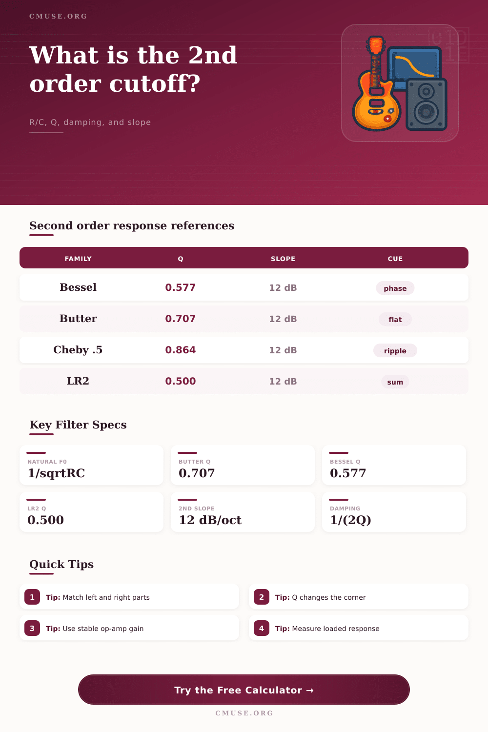
🔎Comparison and Spec Grid
Butterworth
Bessel
Chebyshev
Linkwitz-Riley 2
🧮Filter Family Reference Table
| Response family | Typical Q | -3 dB cutoff relative to f0 | Audio interpretation |
|---|---|---|---|
| Bessel 2nd order | 0.577 | About 0.786 x f0 | Smoother group-delay behavior with a gentler magnitude knee. |
| Butterworth 2nd order | 0.707 | 1.000 x f0 | Maximally flat magnitude response and the common -3 dB reference. |
| Chebyshev 0.5 dB | 0.864 | About 1.231 x f0 | Sharper knee with small passband ripple and some resonant lift. |
| Chebyshev 1 dB | 0.956 | About 1.389 x f0 | More selectivity and more ripple; useful when separation matters. |
| Linkwitz-Riley 2nd order | 0.500 | About 0.644 x f0 | Often used where acoustic summing and polarity relationships matter. |
📐Sallen-Key Formula and Component Table
| Quantity | Formula used here | What changes it | Design caution |
|---|---|---|---|
| Natural frequency f0 | 1 / (2 x pi x sqrt(R1 x R2 x C1 x C2)) | Any timing R or C value | Use measured parts for stereo matching and final verification. |
| Q factor | sqrt(R1R2C1C2) / (C2(R1+R2)+C1R1(1-K)) | Ratios plus gain K | High K values can make the section sensitive or unstable. |
| Damping ratio | zeta = 1 / (2Q) | Target family and component ratios | Lower damping means more resonance around the knee. |
| Equal-value gain target | K = 3 - 1 / Q | Desired Q | Only exact when R1 = R2 and C1 = C2 in this simplified reference. |
| Far stopband slope | 12 dB/oct per section | Number of cascaded sections | Real op-amps, drivers, and loading can limit the ideal slope. |
🎼Preset Planning Table
| Preset | Target f0 | Response family | Starting R/C idea |
|---|---|---|---|
| Studio Sub 80 Hz LR2 | 80 Hz | Linkwitz-Riley Q 0.500 | Matched 0.1 uF capacitors with about 19.9 k timing resistors. |
| Monitor Woofer 2.2 kHz | 2.2 kHz | Butterworth Q 0.707 | 10 nF timing capacitors with about 7.2 k equal resistors. |
| Butterworth 1 kHz Active | 1 kHz | Butterworth Q 0.707 | 10 nF capacitors and about 15.9 k equal timing resistors. |
| Bessel Vocal Smooth | 6 kHz | Bessel Q 0.577 | 4.7 nF timing capacitors and compact equal resistor values. |
| Chebyshev Synth Bright | 1.8 kHz | Chebyshev 0.5 dB | 10 nF timing capacitors with gain raised for a sharper knee. |
| Anti-Alias 18 kHz | 18 kHz | Butterworth Q 0.707 | 1 nF timing capacitors and short, low-noise signal routing. |
| Guitar Cab 5 kHz | 5 kHz | Bessel Q 0.577 | 4.7 nF capacitors for a gentle cabinet-style high roll-off. |
| CV Smoother 20 Hz | 20 Hz | Linkwitz-Riley Q 0.500 | Larger capacitors and high resistors for slow control smoothing. |
📈Q, Damping, and Slope Behavior
| Q range | Damping ratio | Cutoff behavior | Practical check |
|---|---|---|---|
| 0.45 to 0.55 | 1.11 to 0.91 | Very damped, no peaking, -3 dB point sits below f0. | Good for crossover summing or conservative protection filters. |
| 0.56 to 0.65 | 0.89 to 0.77 | Gentle shoulder with smoother transient behavior. | Useful when phase feel matters more than a sharp knee. |
| 0.66 to 0.75 | 0.76 to 0.67 | Classic Butterworth region, flat passband, f0 near -3 dB. | General-purpose choice for many active audio filters. |
| 0.80 to 1.10 | 0.63 to 0.45 | Sharper knee with possible passband lift or resonance. | Listen for ringing and check op-amp stability margin. |
| Above 1.10 | Below 0.45 | Strong resonant peak before the low-pass roll-off. | Use intentionally for synth tone or measured narrow effects. |
📚Second-Order Design Notes Grid
When you are designing a second-order low-pass filter, the way in which a second-order low-pass filter rolls off the signal is one of the important design considerations. Second-order low-pass filters provides a relatively gentle yet decisive cut in the audio frequencies that pass through the filter; the precise frequency at which the second-order low-pass filter begins to cut the high frequencies is dependent upon the interaction of the components that make up the second-order low-pass filter. Each of the parameters that relate to the response of a second-order low-pass filter (the natural frequency, the Q factor, and damping) is related to one another, such that changing one of those parameter will have an effect upon the other parameters.
Second-order filters are more complex than single-pole low-pass filters, yet are less complex than third-order or higher filters. For these reasons, people often employ second-order filters in speaker systems (as crossovers) and synthesizer circuits. Second-order filters provides twelve decibels of attenuation of high frequencies per octave, which is often an adequate amount for these applications.
How Second-Order Low-Pass Filters Work
Moreover, twelve decibel attenuation per octave does not introduces excessive phase shifts within the signal. Second-order filters with natural frequencies set to a particular value will have three-decibel points at a specific frequency; the actual frequency at which the filter begins to roll off is dependent upon the Q factor of the filter. Higher Q factors will result in the three-decibel point moving closer towards the natural frequency, and will provide a small lift of gain in the frequencies just before the three-decibel point begins to roll off.
Lower Q factors will result in the three-decibel point moving away from the natural frequency, and will reduce any lift of gain that may be provided at high Q factors. Thus, the sound produced by a filter with a high Q factor will sound different than that of a filter with a lower Q factor, even if each is set to the same natural frequency. The values of the components within a second-order low-pass filter are important in that the component values will determine both the natural frequency and the Q of the filter.
For instance, in a Sallen-Key topology for a second-order filter, the two values of resistors and the two values of capacitors will determine both the natural frequency at which the filter rolls off, and the Q factor of the filter. Using resistors of the same value will simplify the calculations for designing the filter to achieve a desired Q factor, but will also make the filter sensitive to any drift in the values of the capacitors. In a stereo sound system, where the left and right channels must have the same cutoff frequencies, any drift in the capacitors will shift the frequencies at which the channels roll off; this shift can be significant if any capacitors drift in value.
The audio engineer must make another design decision regarding the response of the filter to frequencies within the audible range. For example, Butterworth filters has a flat response within the audible range; the three-decibel point for a Butterworth filter will lie at the natural frequency of the system. Bessel filters have a gentler roll-off within the audible range; this gentler roll-off provides more even group delay of the audible range.
Linkwitz-Riley filters are often used when two filters must combine with one another to form a sound system; Linkwitz-Riley filters will create a six-decibel dip in the three-decibel point at the natural frequency of the system. Chebyshev filters will create a sharper roll-off of high frequencies (as compared to Butterworth or Bessel filters), but will also create a ripple in the audible frequencies. Chebyshev filters are often used for synthesisers where a decisive roll-off of high frequencies is required; however, they are less forgiving of loadings within the audible range.
Another factor that impacts the loading of a second-order low-pass filter is not accounted for in any mathematical equation for designing the filter. For example, the impedance of a speaker driver is not constant; it changes with the frequency of the signal being played through the driver, and it also changes with the excursion of the driver’s cone. Furthermore, the impedance seen by the output of a guitar amplifier is not constant; it will change depending upon which patch cord is inserted into the amplifier that connects it to the guitar.
Thus, the response curve of a filter will not match the response that is measured with a signal meter directly at the input of the effect box. Therefore, measurement of the response of the system with a loaded component is required. While a filter design calculator may account for component tolerances, it cannot account for loading changes that result from temperature changes within the components of the filter, or supply changes to the op-amps that is present in many second-order filter designs.
The slope of a filter can be changed by cascading filter sections in series with one another. However, cascading filter sections does not change the underlying mathematics that describe the frequency response of each individual filter section. Thus, cascading two identical filter sections will result in a filter that attenuates high frequencies at a rate of twenty-four decibels per octave.
Moreover, cascading two identical filters will result in a steeper shoulder to the roll-off of high frequencies. However, unless the Q factors of the two filter sections is matched to one another, the combination of the two filters may exhibit a dip at the natural frequency of the system if the natural frequencies are set to the same values. A filter design calculator can be used to determine the attenuation of a signal at a particular frequency after cascading two or more filter sections; the calculator can also be used to determine whether cascading additional filter sections will help or harm the performance of the filter.
Most audio engineers will design second-order filters with two or three filter sections; most applications do not require the steep roll-off of a brick wall filter. The skill in the design of second-order filters is in the decision as to which parameter is the most important for the specific task that the filter will be used to accomplish. For instance, protecting a tweeter from high frequencies may require one set of parameters to be emphasized over another, as compared to shaping the sound of a synthesizer.
Higher Q factors produce a small lift to the frequencies just before the three-decibel point in a second-order filter; such lift may be important for the sound of a synthesizer that is to be processed through a relatively high-Q filter. Thus, the design calculator helps to remove the need for audio engineers to perform mathematical calculations; they can focus instead upon the various design decisions that must be made. Once the components for the second-order filter have been purchased and placed upon a workbench, the designer may make small adjustments to the values of the resistors to fine-tune the performance of the filter.
While the mathematical relationships between each parameter will remain the same, the designer will be able to tune the second-order filter in relation to another parameter (such as sound level, or the sound of another component in a sound system). Thus, the design settles when the audio engineer moves from the design phase to the verification phase.