Limiter Calculator
Estimate threshold, ratio, ceiling, gain reduction, output headroom, LUFS shift, and true-peak risk before pushing a master or mix bus limiter.
🎚 Limiter Presets
🎛 Limiter Inputs
LUFS estimates use input RMS as a practical proxy. Confirm final loudness and dBTP with a loudness meter after rendering.
📊 Limiter Spec Snapshot
📝 LUFS and True-Peak References
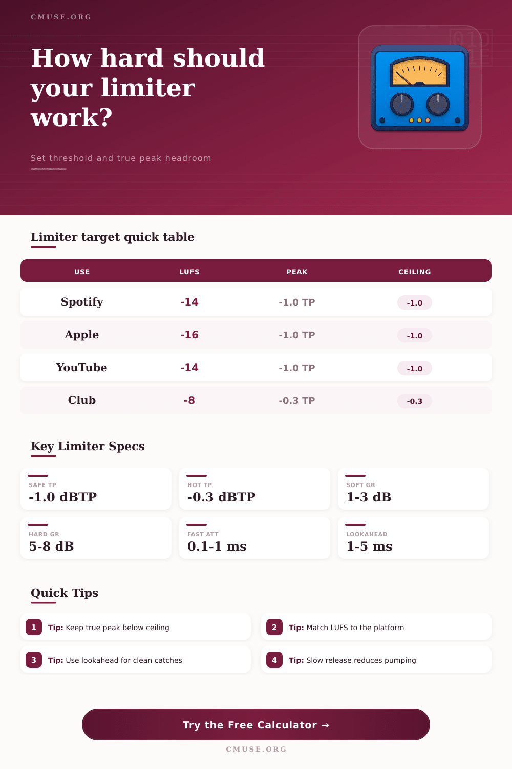
| Platform / Use | Common LUFS Aim | True Peak Reference | Limiter Note |
|---|---|---|---|
| Spotify Normal | -14 LUFS | -1.0 dBTP | Moderate GR keeps codec headroom |
| Apple Music | -16 LUFS | -1.0 dBTP | Sound Check favors dynamic masters |
| YouTube Music | -14 LUFS | -1.0 dBTP | Check loudness after upload encode |
| Podcast Voice | -16 to -18 LUFS | -1.0 dBTP | Use slower release for speech body |
| Club Playback | -9 to -7 LUFS | -0.3 dBTP | Expect heavier GR and less headroom |
⚙ Attack, Release, and Lookahead Table
| Mode | Attack | Release | Lookahead |
|---|---|---|---|
| Transparent Master | 2-8 ms | 180-400 ms | 3-6 ms |
| Punchy Mix Bus | 0.5-2 ms | 60-150 ms | 1-3 ms |
| Vocal Safety | 1-5 ms | 120-260 ms | 3-5 ms |
| Hard Brickwall | 0.1-1 ms | 30-100 ms | 1-2 ms |
📡 Limiter Comparison Grid
🎵 Preset Outcome Table
| Preset | Input Peak | Target LUFS | Ceiling |
|---|---|---|---|
| Spotify Master | -3.5 dBFS | -14 LUFS | -1.0 dBTP |
| Club DJ Hot | -1.1 dBFS | -9 LUFS | -0.3 dBTP |
| Broadcast Dialogue | -5.5 dBFS | -18 LUFS | -1.5 dBTP |
| Acoustic Preserve | -6.2 dBFS | -20 LUFS | -2.0 dBTP |
🔍 Gain Reduction Reading Table
| GR Amount | Sound Impact | Meter Watch | Adjustment |
|---|---|---|---|
| 0-1 dB | Safety only | Rare peak taps | Keep ceiling as set |
| 1-3 dB | Clean density | Stable loud parts | Good for streaming |
| 3-6 dB | Audible control | Release movement | Slow release or raise threshold |
| 6 dB+ | Heavy limiting | Transient loss | Reduce drive or split stages |
A limiter is a tool that audio engineer use to manage the loudness of a track. Engineers use a limiter because they want there track to be loud enough for the target platforms; however, they do not want to ruining the transient characteristics of the track. A limiter calculator is a tool that estimate what the loudness of the track will be with specific limiter setting.
A limiter calculator will provide an estimate of the gain reduction that the limiter will apply to the track. A limiter calculator will also provide an estimate of the output peak level of the track. Furthermore, a limiter calculator will provide an estimate of whether the tracks true peak will exceed the ceiling level after it is encode.
What a Limiter Calculator Does
While a limiter calculator isnt a replacement for the engineer’s ears to listen to a track, a limiter calculator can remove the need to guess at the loudness settings of the limiter. The input that an engineer uses for the limiter calculator are just as important as the outputs. The peak level of the tracks loudest moment is one input for the limiter calculator.
The RMS level of the track before it is limited is another input. The target loudness in LUFS is another setting. The threshold, ratio, and ceiling level of the limiter are three settings that will determine the loudness of the track.
The attack and release settings for the limiter will allow the engineer to control how quick the limiter acts upon the track. The lookahead setting will allow the limiter to anticipate loud sounds in the track. The oversampling setting will allow the limiter to catch inter-sample peak.
The channel character can be adjusted to affect the behavior of the limiter. If any of the input parameter are changed, the estimated gain reduction and the output peak will change. These two settings is detailed but difficult to follow with the adjustment of each parameter.
The outputs of the limiter calculator will allow engineers to see what the settings will do to their track. The gain reduction will allow engineers to see how much the loudest part of the track will be reduced. The output peak is another way to see the effect that the limiter settings has upon the track.
The estimated LUFS levels will tell the engineer if the track will reach the target loudness. The true-peak risk will allow engineers to see if the track will clip on the target platform. These four settings are essential for understanding how the limiter settings will affect the final product.
These outputs allow engineers to compare two different limiter settings without rendering the track. Reference tables allow engineers to see the targets of loudness for different types of media. For example, music that is to be played on a streaming platform will have a loudness of around minus fourteen LUFS and a true-peak ceiling of minus one decibel.
Club mix will have more gain reduction and a higher ceiling as the clubs systems can take the louder levels. Content that is used for broadcast or spoken word will have a lower target loudness to ensure that the dialogue in the track is easily understood. While these values are not rules that will apply to all song, they do provide engineers with a good starting point for the loudness settings.
The limiter calculator will allow engineers to see how the settings will compare to these references. The attack and the release settings are important beyond the loudness of the track. Fast attack settings will catch loud sound in the track.
However, they will also remove the transient information from loud sounds like drums. A slow release will preserve the transient information in the drums but will also allow the transient to pass through the limiter settings. The lookahead setting will allow for the limiter to anticipate loud sounds in the track.
Thus, if the lookahead is shorter than the attack time, the limiter will essentially be guessing at the loud sounds instead of catching them. The true-peak level will allow engineers to see if the signal will exceed zero decibels and create clipping on the target platform. True peaks can occur even if the signal is always below zero decibels on the sample-peak meter.
The oversampling setting will allow the limiter to catch these inter-sample peaks. The higher the oversampling selected for the limiter, the more better the chance that the limiter setting will catch these inter-sample peaks. The safety margin that is applied to the output peak level of the track can help to protect the signal from clipping when it is passed through lossy audio codecs.
Stereo linking will allow the engineer to maintain the stereo image of the track. If the channels are fully linked, the limiting process will not alter the stereo image. However, if the channels are unlinked, the stereo image may be too wide for the target platform or the center image may “pump.” The percentage control will allow engineers to fine-tune the stereo link amount.
Many engineers makes mistakes with their limiter settings. One of the most common mistakes is using a threshold that is too low to create too much gain reduction. Another mistake with the limiter settings is using an extremely fast release time.
A fast release will work well for short periods; however, if used for long periods the song will become fatiguing for the listener. A third mistake is failing to ensure that the ceiling level and the true-peak margin are balanced to avoid clipping on the target audio platform. Such mistakes will not be prevented by using a limiter calculator, but they will become visible to the engineer prior to rendering the audio file.
The limiter calculator allows engineers to separate the variables that they can adjust from those that become clear after the encoding process. Engineers must still use their ears to mix a song. However, a limiter calculator can remove the need to perform mental calculation and to create test rends of a song.
Through the use of a limiter calculator, engineers will understand where the limiter will push the song and where it will allow the song to remain as it is.