IIR Filter Calculator
Design audio biquad IIR filters, normalize coefficients, inspect pole radius, and check stability before exporting DSP settings.
🎛Filter Presets
📐IIR Filter Inputs
Normalized biquad coefficients
🧮Formula Reference
w0 = 2*pi*f0/Fs, alpha = sin(w0)/(2Q), and normalized denominator a0 = 1. Stability is tested from the denominator roots of z^2 + a1*z + a2 = 0; a biquad is stable when every pole radius is below 1.
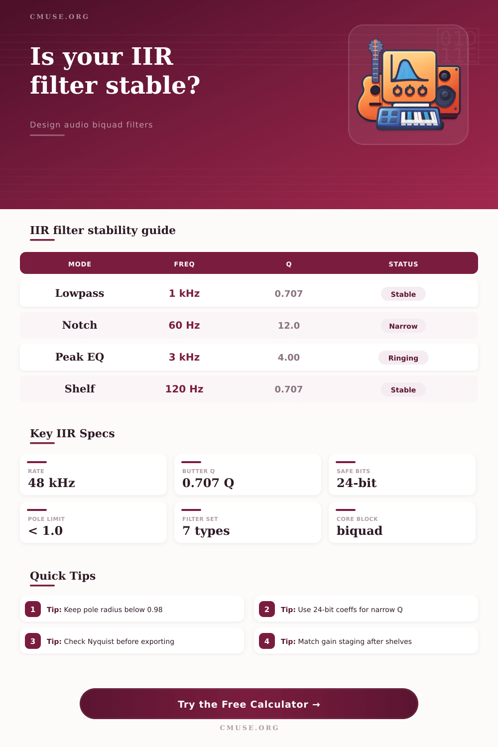
📊Filter Spec Grid
📝IIR Type Comparison
| Filter type | Main control | Typical audio use | Stability note |
|---|---|---|---|
| Lowpass | Cutoff and Q | Synth tone, sub routing, anti-harshness | High Q can ring near cutoff |
| Highpass | Cutoff and Q | Rumble removal, vocal cleanup | Very low cutoff needs more precision |
| Bandpass | Center and Q | Telephone tone, resonant emphasis | Bandwidth shrinks as Q rises |
| Notch | Center and Q | Hum, whistle, room mode removal | Narrow notches are quantization sensitive |
| Peaking EQ | Gain, center, Q | Corrective and creative equalization | Boost needs headroom |
| Shelf EQ | Gain and corner | Bass lift, air lift, tilt shaping | Large boosts can overload cascades |
🎯Q and Bandwidth Table
| Q value | Octave width | Behavior | Common setting |
|---|---|---|---|
| 0.500 | About 2.54 oct | Wide and gentle | Tone shaping |
| 0.707 | About 2.00 oct | Butterworth response | Crossovers and cleanup |
| 1.414 | About 1.00 oct | Focused but musical | Presence shaping |
| 4.000 | About 0.36 oct | Narrow correction | Room or resonance trim |
| 12.000 | About 0.12 oct | Very narrow | Hum or whistle notch |
🔍Precision and Stability Table
| Coefficient precision | Step size | Best use | Risk area |
|---|---|---|---|
| 16-bit fixed | 1 / 65536 | Simple tone filters | Low frequency or high Q |
| 20-bit fixed | 1 / 1048576 | Embedded audio control | Deep notches |
| 24-bit fixed | 1 / 16777216 | Most audio DSP export | Extreme resonances |
| 32-bit fixed | 1 / 4294967296 | High precision processors | Internal headroom |
| Float | Runtime mantissa | Plug-ins and DAWs | Denormals near silence |
📈Preset Design Table
| Preset | Type | Frequency | Design intent |
|---|---|---|---|
| Vocal Highpass | Highpass | 80 Hz | Remove plosives and rumble |
| Bass Lowpass | Lowpass | 5 kHz | Keep bass cabinet tone smooth |
| Room Notch | Notch | 60 Hz | Reduce mains hum or room mode |
| Presence Peak | Peaking EQ | 3 kHz | Add focused vocal intelligibility |
| Telephone Bandpass | Bandpass | 1.2 kHz | Approximate narrow voice bandwidth |
An Infinite Impulse Response (IIR) filter use feedback because teh output of the IIR filter is fed back into the input of an IIR filter. Because of this feedback mechanism, it is possible for the IIR filter to become unstable. An unstable IIR filter will produce digital noises instead of the mathematical signal that the filter are suppose to create.
Furthermore, the instability of the IIR filter can lead to damaged speaker or ruined audio mixes. The stability of an IIR filter can be determined by the location of the poles of the IIR filter on a complex plane. The stability of the IIR filter depend upon whether the poles of the IIR filter lie within the unit circle.
Why IIR Filters Can Become Unstable
If the radius of a pole is less than one, the pole is stable. If the radius of a pole is greater than one, the pole is unstable. In the real world, all processors has some form of rounding in their operations.
If the radius of a pole of an IIR filter is very close to one, such as 0.999, the rounding that occurs with all real world processors can lead to the pole move outside of the unit circle. If the pole moves outside of the unit circle, the IIR filter will be unstable. The Q factor of a filter determine how much the filter will “ring” at the cutoff frequency.
High values of the Q factor will lead to a resonant peak at the cutoff frequency. A Butterworth response of a filter will have a flat response in the passband, but high values of the Q factor will move the poles of the IIR filter more closer to the edge of the unit circle. As the poles of an IIR filter come closer to the edge of the unit circle, the ringing decay time of the IIR filter increase.
Thus, an increased ringing decay time will cause the IIR filter to take longer to settle after a transient. The sample rate at which an IIR filter operates will impact the behavior of the IIR filter. The sample rate impacts the digital mapping of the IIR filter.
For instance, if the digital filter has a cutoff frequency that is close to the Nyquist limit, which is half the sample rate, the digital mapping of the IIR filter begins to warp. Thus, the behavior of an IIR filter at 96 kHz will be more different than the behavior of an IIR filter at 44.1kHz. One of the factors that the designer must take into consideration for the stability of an IIR filter is the precision of the calculations of the IIR filter.
The precision of the calculations is dependent upon whether floating point or fixed point math are used to calculate the IIR filter. The majority of Digital Audio Workstations use floating point math, so most users of DAWs wont experience issues related to quantization. However, many embedded DSPs and audio effect pedal will use fixed point math.
For instance, many use 16-bit or 24-bit fixed point math. Using a 16-bit fixed point processor to implement a high Q notch filter may lead to problems because the 16-bit representation of the coefficients dont have enough resolution to maintain the position of the pole of the filter. Thus, the pole may move outside of the unit circle.
An additional factor that will impact the signal that is created by an IIR filter is the headroom for the signal. Headroom is a factor to consider if the frequency is being boost with a peaking EQ. If a peaking EQ boosts the frequency, the internal signal of the digital device will increase.
If the internal signal is too high, it may lead to internal clipping. Internal clipping will introduce digital distortion into the signal, which is a form of noise that cant be fixed with makeup gain. To ensure that the IIR filter is stable, the designer must find a balance between musicality and mathematical safety.
To ensure that the audio remains clean, the designer can check the pole radius of the IIR filter and the decay time of the IIR filter before finalizing the parameters of the IIR filter. By checking the pole radius and the decay time, the IIR filter designer can determine how close each pole of the filter is to the edge of the unit circle. By determining the distance of each pole to the edge of the unit circle, the IIR filter designer can ensure that they avoids the potential for instability caused by rounding error.