Audio High-Pass Filter Calculator
Design a notch filter for hum, buzz, resonant peaks, or feedback using twin-T, RLC, or DSP biquad math.
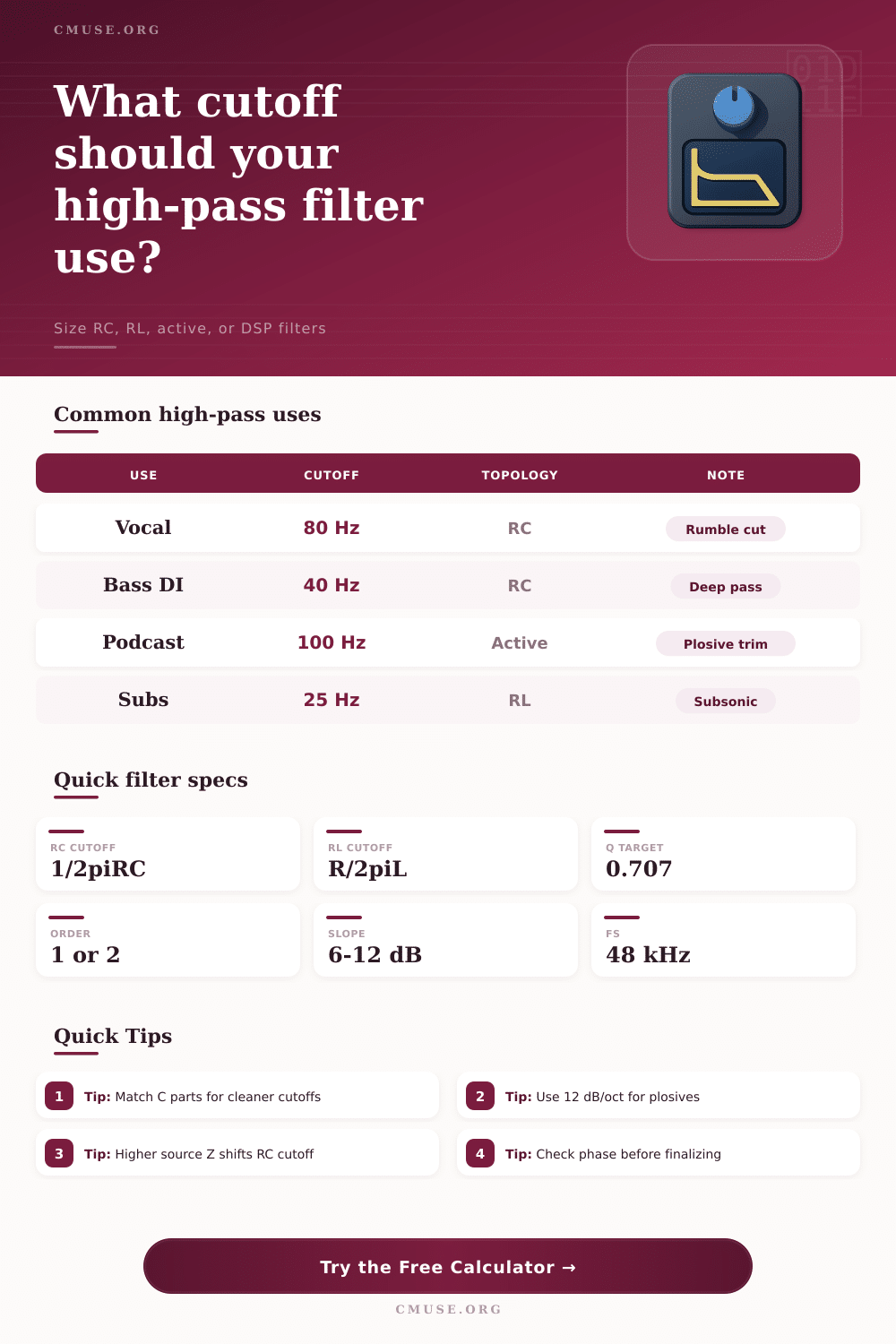
🎧 High-Pass Presets
⚙ Filter Setup
📊 High-Pass Spec Grid
📖 Reference Tables
| Use | Cutoff | Topology | Note |
|---|---|---|---|
| Vocal rumble | 70-100 Hz | RC | Cleaner low end |
| Podcast plosives | 80-120 Hz | Active | Speech clarity |
| Bass DI cleanup | 30-50 Hz | RC | Keep fundamentals |
| PA protection | 20-40 Hz | Digital | Subsonic guard |
| Kick drum track | 25-40 Hz | RL | Rumble trim |
| Guitar amp input | 100-180 Hz | RC | Brighten tone |
| Overheads | 120-180 Hz | Active | Floor rumble |
| Master bus DC | 10-25 Hz | Digital | Invisible protection |
| Target | R | C / L | Comment |
|---|---|---|---|
| 20 Hz | 10 kΩ | 0.80 uF | Mastering HP |
| 40 Hz | 10 kΩ | 0.40 uF | Bass safety |
| 80 Hz | 10 kΩ | 0.20 uF | Voice cleanup |
| 120 Hz | 8.2 kΩ | 0.16 uF | Speech trim |
| 200 Hz | 6.8 kΩ | 0.12 uF | Thin sources |
| 500 Hz | 3.3 kΩ | 0.10 uF | Special effect |
| Topology | Order | Strength | Best use |
|---|---|---|---|
| Passive RC | 1 | Simple | Coupling caps |
| Passive RL | 1 | Robust | Speaker loads |
| Sallen-Key | 2 | Flat or damped | Active audio |
| Digital biquad | 2 | Precise | DAW or DSP |
| Order | 1 octave down | 2 octaves down | Phase at fc |
|---|---|---|---|
| 1st | -7 dB | -13 dB | 45 deg |
| 2nd Butterworth | -12 dB | -24 dB | 90 deg |
| 2nd damped | -10 dB | -20 dB | Near 90 deg |
| Digital biquad | Matches coeffs | Matches coeffs | Coeff dependent |
💡 Practical Tips
Low-frequency rumbles refers to an unwanted noise in the audio signal. This type of rumble is often caused by air handlers or the vibration of the stage on which the vocalist is perform. This rumble take up headroom in the mix.
To remove this rumble, audio engineers uses a high-pass filter. By using a high-pass filter, engineers can remove the rumble noise from audio sources. However, they must decide on the cutoff frequency of a high-pass filter and the slope of the filter.
How to Remove Low Rumble with a High-Pass Filter
If the cutoff frequency is set too highly, the warmth of the kick drum and the low-mid frequencies of the guitar can be lost from the master mix. Additionally, if the cutoff frequency is set too low, the speakers will only amplify the noise and the listener will not hear it. The engineers can decide the cutoff frequency of high-pass filter based off the sound source.
For instance, vocals will have a high-pass filter set to 80 Hz to remove the floor thump. However, a subwoofer may require a high-pass filter set to 25 Hz. Passive RC network can be used to create a high-pass filter.
A passive RC network consists of a series capacitor and a load resistance. These types of RC networks are first-order filter. The slope of a first-order filter is 6 dB per octave.
First-order filters are preferred because they do not cause large phase shifts in the audio signal. However, the equivalent resistance from the source and the load will determine the cutoff frequency of the passive RC network. Thus, when using a passive RC network, engineers must test the cutoff frequency of the RC network with the lengths of the actual cable.
RL version of high-pass filters use inductors instead of capacitors. RL version of high-pass filters are often used for speaker crossovers for the robustness of inductors against component drift. Active filters is more complex than passive RC networks.
Active filters can use op-amps to produce second-order filters. The slope of a second-order filter is 12 dB per octave. Additionally, active filters can use Sallen-Key topology to isolate the audio source from the filter.
The quality factor or Q factor of the active filter can be adjusted. The Q factor determine the damping of the active filter. A Q factor of 0.707 will produce a Butterworth filter.
A Butterworth filter has the property of being flat in its passband. Digital biquads is another type of high-pass filter, and they use coefficients that are normalized to the sample rate of the digital signal processors involved. Component tolerance is another consideration when building a high-pass filter.
If the components have a 5% tolerance, this could mean that the cutoff frequency of the high-pass filter could shift by 10 Hz. This might mean that the high-pass filter could miss the correct frequency necesary to remove rumble from the audio signal. Load impedance also affects the performance of passive high-pass filter as it pulls the corner frequency of the filter lower.
Thus, it is necessary to use a high input impedance device on the following stage in the audio signal processing chain. The phase response of a high-pass filter is another tradeoff to consider when using such a filter. A first-order high-pass filter will introduce a phase lag of 45 degrees at the cutoff frequency of the filter.
Using high-pass filters can introduce smearing of the transient in the audio signal. A second-order high-pass filter will introduce a phase lag of 90 degrees at the filter’s cutoff frequency. Furthermore, using second-order high-pass filter can introduce a bump in the group delay of the signal.
Both of these effects can be seen by listening to the attack of a sound through the high-pass filter. Since the attenuation of a high-pass filter builds slowly, using many high-pass filters in series can introduce phase problem. Depending on the application of the high-pass filter to the audio signal, there are different recommended cutoff frequencies for those filter.
For instance, using a high-pass filter at 120 Hz can help remove rumble from signals picked up by overhead microphone without thinning the tone of the cymbals in the band. Using a high-pass filter at 40 Hz can help remove subsonic frequencies from signals coming from a bass DI box without removing the fundamental frequency from the sound of the bass. Using a high-pass filter at 20 Hz on a mastering bus can help remove a DC offset from the signal.
Finally, using a high-pass filter at 100 Hz on guitar inputs will make the guitar amplifier sound more bright. Another parameter for a high-pass filter is the Q factor. Low values for the Q factor will produce a broad rolloff of frequencies at the cutoff frequency of the high-pass filter, giving the sound a more natural response.
Higher values of the Q factor will create a sharper rolloff of frequencies at the cutoff frequency, which might be desirable for other types of protection circuit. In a digital system, the sample rate will determine the parameters of the high-pass filter. A sample rate of 48 kHz will provide enough headroom to avoid aliasing issues in the signal.
A calculator can determine the settings for the high-pass filter since the calculator can solve for loaded cutoffs in various types of filter. A calculator will find the time constant, the octave attenuation, and the corner frequency of the high-pass filter. Since high-pass filters are not meant to erase all of the low frequency in the sound being processed, high-pass filters are meant to reclaim clarity of the signal by removing the noise floor from the signal.