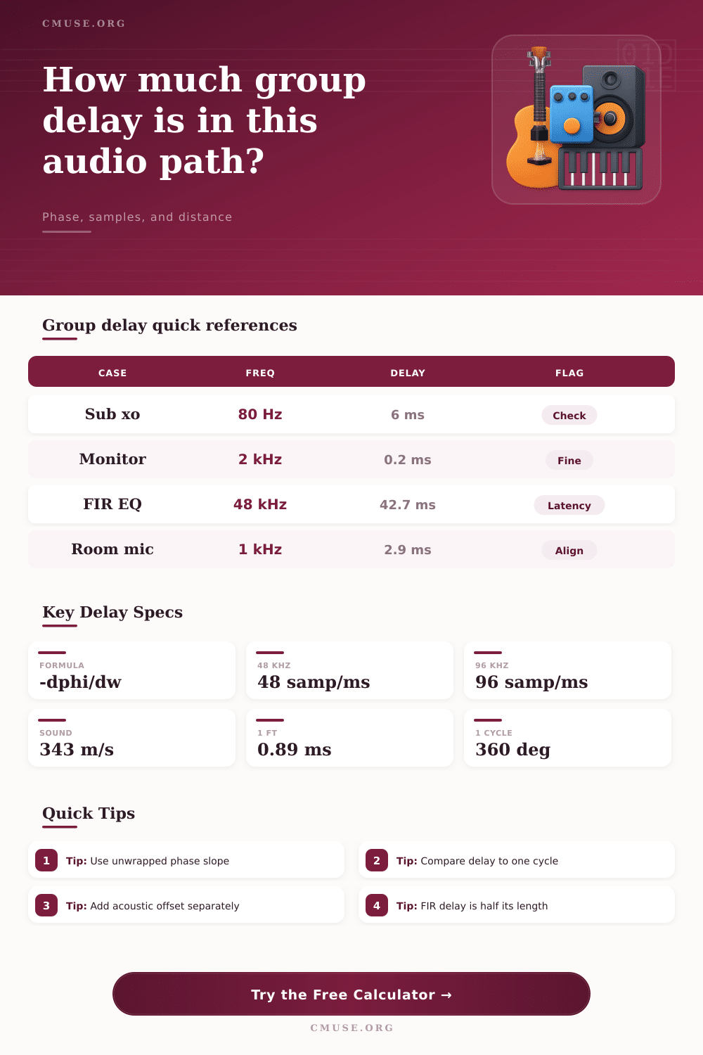
Group Delay Calculator
Estimate audio group delay from phase slope, filter type, FIR length, acoustic spacing, and sample rate.
🎵Presets
🎛Calculator Inputs
For measured data, use unwrapped phase. A falling phase trace normally gives a positive group delay.
📊Reference Specs
| Calculation type | Core formula | Best use | Watch item |
|---|---|---|---|
| Measured phase slope | -(Δphase / 360) / Δfrequency | Analyzer exports and crossover traces | Phase must be unwrapped |
| Linear phase FIR | (taps - 1) / (2 x sample rate) | Convolution EQ, FIR crossovers, limiters | Latency rises with tap count |
| First-order all-pass | 1 / (pi x fc x (1 + r²)) | Small phase trims near one corner | Delay halves above and below fc |
| Second-order all-pass | Q / (pi x f0) near center | Sharper phase rotation around one band | High Q narrows the delay peak |
| Acoustic offset | distance / sound speed | Driver depth, mic spacing, sub alignment | Temperature changes sound speed |
🎧Common Audio Cases
| Scenario | Typical band | Delay range | Practical interpretation |
|---|---|---|---|
| Subwoofer crossover | 50 to 120 Hz | 3 to 15 ms | Often audible as weak or lumpy summing if unmatched |
| Studio monitor crossover | 1.5 to 3 kHz | 0.05 to 0.6 ms | Small in time, but still meaningful in phase |
| Ported enclosure tuning | 30 to 70 Hz | 8 to 30 ms | Delay peaks around the tuning region |
| Room microphone spacing | Full range | 0.9 ms per ft | Use samples or milliseconds to line up transients |
| Linear phase mastering EQ | Program wide | 10 to 100 ms | Latency is predictable from tap length |
📐Frequency Delay Grid
| Frequency | One cycle | 45° tolerance | 90° tolerance |
|---|---|---|---|
| 40 Hz | 25.00 ms | 3.13 ms | 6.25 ms |
| 80 Hz | 12.50 ms | 1.56 ms | 3.13 ms |
| 250 Hz | 4.00 ms | 0.50 ms | 1.00 ms |
| 1 kHz | 1.00 ms | 0.13 ms | 0.25 ms |
| 4 kHz | 0.25 ms | 0.03 ms | 0.06 ms |
💡Calculation Tips
Group delay refer to the phenomenon where the different frequency within an audio signal travel at different speeds through an audio system. Because different frequencies within an audio signal experiences more delay than others, the signal can become smear out. As a result, low frequencies may arrive at the listener at a different time than mid frequencies, making the audio signal sound disconnectedly.
For instance, an low frequency of a kick drum may not be heard at the same time as the bass note due to group delay. Group delay is mathematically define as the time derivative of phase. Phase refers to the position of a sound wave within the cycle of that sound wave at a specific moment in time.
What Is Group Delay in Sound Systems
Group delay measure the movement of the envelope of that sound wave. When a person utilize an equalizer or a crossover, those equalizer and crossovers shift the phase of the audio signal. If the phase is shift in a linear manner, each frequency will experience the same delay, which is often not perceivable by human ear.
However, if the phase is not linear shifted, different frequencies will experience different delay. Different amounts of delay occurs most frequent when a person employs filter, such as a Butterworth filter or a Linkwitz-Riley filter. Both of these filter types has the potential to alter the phase of a sound signal rapid near the corner frequency of that filter.
Such rapid alteration to the phase of a sound signal create alteration to the group delay of that signal, as well. Thus, frequencies that is present near the corner frequency of that filter will experience a different amount of delay than those that are located away from that corner frequency. This different amount of delay for the frequencies near the corner frequency relative to the other frequencies is why sounds reproduced through a subwoofer crossover can feel disconnect from the remaining sound system’s mid-frequency sound.
To control the group delay of a system, a person must understand how filter can impact the phase of a sound system. More specific, if a person employ a crossover to separate the low frequencies from the mid frequencies of an audio system, the crossover will introduce phase shift to those frequencies. These phase shift create group delay, and group delay create a time difference between each of those sound system’s frequency.
Thus, if a person notice that the low frequencies of the system are smear relative to the other frequencies of the system, the person may be experiencing group delay that is create as a result of the phase shift of the system’s crossover or equalizer. For these reason, group delay is both a result of the phase shift of those filters, as well as a result of the difference in timing of each of the sound system’s frequencies.