Ground Loop Hum Calculator
Estimate ground loop hum voltage, circulating shield current, magnetic pickup, hum frequency, common-mode rejection, and isolation improvement for studio, stage, broadcast, and hi-fi audio links.
Load a real audio wiring scenario, then adjust the measured AC voltage between chassis, cable shield resistance, loop area, mains frequency, input CMRR, and isolation attenuation.
Ground Loop Hum Breakdown
Iloop = Vground / (Rshield + Rbond)Vinduced = 2 x pi x f x B x areaVdrop = Iloop x Rshield x couplingVaudio = (Vdrop + Vinduced) / 10^(dB/20)Base mains hum frequency
Common rectifier ripple band
0 dBu reference voltage
0 dBV reference voltage
Ten times voltage rejection
One thousand times rejection
Magnetic field input scale
Low shield resistance region
| Cable Or Link Type | Typical Shield Resistance | Use In Calculator | Hum Note |
|---|---|---|---|
| Short balanced patch cable | 0.020 to 0.040 ohm/m | 0.030 ohm/m | Usually low current drop, but still vulnerable if chassis voltage is high. |
| Long stage microphone cable | 0.035 to 0.080 ohm/m | 0.055 ohm/m | Long paths make shield voltage drop easier to measure. |
| Thin unbalanced instrument lead | 0.060 to 0.160 ohm/m | 0.100 ohm/m | High coupling makes small shield drops audible. |
| Multicore snake channel shield | 0.020 to 0.070 ohm/m | 0.045 ohm/m | Shared infrastructure can connect distant safety-earth points. |
| Phono or hi-fi ground lead | 0.080 to 0.250 ohm/m | 0.150 ohm/m | Low signal level means tiny hum voltages can dominate. |
| Region Or Source | Fundamental | Second Harmonic | Typical Audio Clue |
|---|---|---|---|
| 60 Hz mains region | 60 Hz | 120 Hz | Low buzz points to ground loop; smoother buzz often includes ripple. |
| 50 Hz mains region | 50 Hz | 100 Hz | Deep hum often appears below guitar low E at 82.4 Hz. |
| Power supply ripple | 50 or 60 Hz | 100 or 120 Hz | Second harmonic rises when rectifiers and reservoir caps dominate. |
| Lighting dimmer or switcher | Varies | Many harmonics | Buzz becomes sharper and may change with dimmer position. |
| Magnetic transformer pickup | 50 or 60 Hz | Often present | Moving cable loops or transformers changes the reading. |
| Connection Type | Typical Coupling | Typical CMRR | Calculator Starting Point |
|---|---|---|---|
| Balanced line input on XLR or TRS | 1% to 8% | 50 to 90 dB | Use 4% coupling and 65 dB CMRR for normal studio gear. |
| Transformer-balanced input | 0.5% to 4% | 70 to 100 dB | Add 10 to 30 dB isolation when the transformer breaks the loop. |
| Unbalanced RCA or TS link | 40% to 100% | 0 to 20 dB | Use high coupling because shield current shares the signal return. |
| DI box with ground lift | 2% to 15% | 40 to 80 dB | Enter lift attenuation if the DI isolates audio ground from chassis. |
| Phono cartridge input | 20% to 100% | 0 to 30 dB | Use low voltage tolerance because cartridge signal is very small. |
| Mitigation Choice | Typical Attenuation | Best Fit | Calculator Input |
|---|---|---|---|
| Balanced receiver with good CMRR | 40 to 90 dB | Line-level studio and stage connections. | Increase CMRR, leave isolation at 0 dB. |
| Audio isolation transformer | 20 to 60 dB | Stubborn loops between powered devices. | Add 20 to 40 dB isolation attenuation. |
| DI ground lift on instrument feed | 10 to 40 dB | Guitar amp, keyboard, or laptop into console. | Add lift attenuation if the hum drops when lifted. |
| Shorter cable loop area | 3 to 20 dB | Magnetic pickup from transformers or power cables. | Reduce loop area and sometimes cable length. |
| Single rack bond point | 5 to 30 dB | Multiple rack rails or patchbay sleeve paths. | Lower ground voltage or added bond impedance after measuring. |
| Scenario | Starting Inputs | Primary Result To Watch | Useful Threshold |
|---|---|---|---|
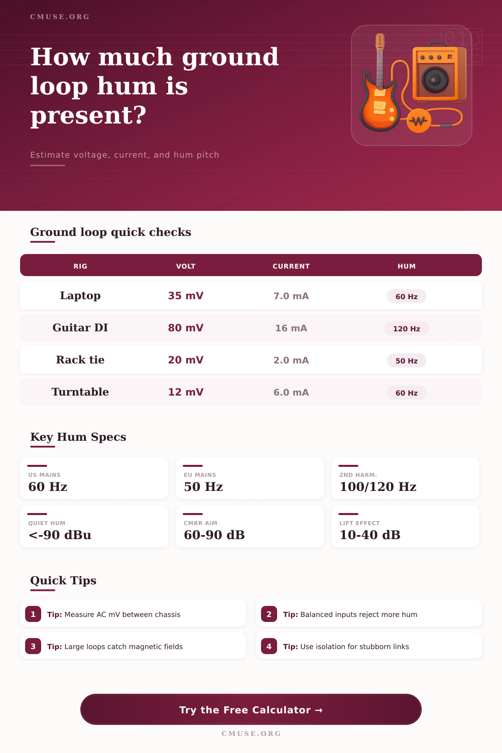
| Laptop interface feeding powered monitors | 30 to 80 mV, 4 to 8 m cable, 60 Hz | Input hum dBu after CMRR. | Below -90 dBu is often quiet in nearfield monitoring. |
| Guitar amp DI to front-of-house | 50 to 150 mV, 10% to 30% coupling, 120 Hz | Loop current and shield drop. | Above 10 mA deserves a lift or transformer check. |
| Rack patchbay between two power strips | 10 to 40 mV, low shield resistance, 50 or 60 Hz | Total rejection and combined hum voltage. | CMRR below 50 dB can expose small loop drops. |
| Turntable into phono preamp | 5 to 25 mV, high coupling, small signal level | Input hum voltage in microvolts. | Microvolt-level hum can be audible after high phono gain. |
| Long stage snake to isolated split | 20 to 100 mV, 20 to 50 m length, 50/60 Hz | Current through shield path. | Use isolation when current and magnetic pickup both rise. |
You know the sound: that annoying low-level constant droning beneath your music, like a bad hangover. For any of us that plugs more than one thing into a wall socket at once, ground loop hum is one of the most ubiquitous audio issues out there. Electricity wants to take the shortest route back home and when two pieces of equipment are plugged into separate circuits, their safety grounds can be at slightly different voltages from each other. This tiny voltage difference result in current flowing through your audio cable’s shield, which then becomes an antenna for mains noise.
After you enter your cable specs and measured chassis voltage, the calculator does all the math for you… No more guesswork about whether you’re dealing with a magnetic or electrical issue. And here’s something most folks don’t realize: the hum isn’t necessarily originating within your equipment; it’s typically right outside the door in the wiring.
How to Fix Hum Noise with This Tool
After entering some information, the calculator calculates the amount of current flowing around that shield and then estimates how much of that current actualy finds its way into your signal path. It then decodes the noise into its constituent parts, i.e., separating the magnetic fields generated by neighboring power supplies or transformers vs. The voltage drop resulting from ground potential differences. Why? Because each need to be addressed different than before.
With the cable plugged in, measure the AC millivolts from the chassis of each device to one another. You’re looking at 30-50 millivolts? Okay, you’ve got yourself a loop. Plug those numbers in (along with the length of your cable and shield resistance) into this handy calculator. The thinner the cable, the greater the resistance, the same current will cause a higher voltage drop.
The calculator takes all these factors and makes an educated guess about how much buzz should of resulted once your mixer has done its best to reject it. The thing is balanced inputs were made to cancel out such interference, but only when the interference strikes both signal wires equally. When the coupling is too great or the loop size too large, it overcome the rejection and lets the buzz right on through.
There’s another problem that gets overlooked: magnetic pickup. You might address the ground voltage problem, but a big loop of wire sitting near a power strip can pick up all sorts of electromagnetic interference. For this reason, the calculator also ask about the area of the loop (how big it is) and any nearby magnetic fields. No matter how good your grounding, a bigger loop will collect more noise. That’s why keeping cable short and twisted up matters so much. It shrinks the physical antenna size, cutting off the interference before it even get into the cable shield.
By flipping the isolation attenuation switch, you’ll see that the result can vary wildly. That’s because this will simulate something like plugging into a DI box or an audio transformer. This breaks the electrical connection from one piece of gear to another. Without a continuous metallic path, the ground current has nowhere else to go so it stop completely.
The reduction in decibel terms is shown right on the calculator and can help guide your decision as to whether full galvanic isolation are necessary or simply a ground lift switch suffices. So don’t unplug the safety ground pin of your power cord thinking you are fixing things. Sure, maybe the hum will go away, but what happens when one of your devices has an internal fault? Your chassis is now live and dangerous.
Use the tool instead to find out where the noise is originating. Is it magnetic induction? Move your cables farther from lamp dimmers and power bricks. Is it shield voltage drop? Change your rack wiring to have all of them tied together on one power strip, or use balanced connections rated for high noise rejection specs.
Remember, we aren’t looking for quiet; we want clean signal integrity while still ensuring safety. With some understanding of the numbers, the hum won’t be a mystery anymore. It will simply become another wiring detail that you can manage. Enjoy your mix again…without that ever-present, nagging buzz in the background.