Flanking Transmission Calculator
Estimate apparent room isolation by summing direct partition energy with sidewall, floor, ceiling, and service-path flanking energy.
| Calculation step | Formula used | Meaning | Calculator output |
|---|---|---|---|
| Direct transmission | tau d = 10^(-R direct / 10) | Converts the direct wall rating into transmitted energy | Direct energy share |
| Flanking path | tau f = n x area factor x 10^(-R path / 10) | Counts repeated side, floor, ceiling, and service paths | Path-by-path energy |
| Total apparent rating | R prime = -10 log10(sum of tau) | Sums energy first, then converts back to dB | Apparent isolation card |
| Field margin | tau design = tau total x (1 + buffer) | Accounts for workmanship, small leaks, and junction variance | Design-adjusted rating |
| Assembly type | Typical direct rating | Mass cue | Best use in calculator |
|---|---|---|---|
| Single stud with one board each side | STC/Rw 39 | 22 kg/m² | Existing practice spaces and light partitions |
| Insulated stud with double board | STC/Rw 46 | 32 kg/m² | Project studios and teaching rooms |
| Resilient channel wall | STC/Rw 52 | 34 kg/m² | Retrofit control rooms with moderate flanking |
| Double stud isolated wall | STC/Rw 62 | 44 kg/m² | Drums, rehearsal rooms, and high isolation work |
| Masonry plus isolated lining | STC/Rw 64 | 185 kg/m² | Studios where junctions are also broken |
| Path family | Weak field value | Controlled value | Energy factor used |
|---|---|---|---|
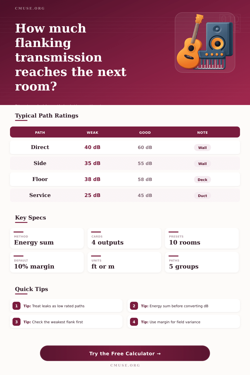
| Sidewall continuation | 35 to 42 dB | 50 to 58 dB | 0.50 per path |
| Floor deck or slab edge | 38 to 45 dB | 52 to 60 dB | 0.65 per path |
| Ceiling void or roof deck | 36 to 44 dB | 52 to 60 dB | 0.60 per path |
| Duct, conduit, gap, or back box | 25 to 35 dB | 40 to 50 dB | 0.10 per path |
| Room scenario | Wall or partition size | Primary target | Likely weak path |
|---|---|---|---|
| Home studio control wall | 10 ft x 8 ft / 3.0 m x 2.4 m | 50 to 55 dB | Sidewall junction |
| Vocal booth partition | 5 ft x 8 ft / 1.5 m x 2.4 m | 45 to 50 dB | Door and service gaps |
| Drum or rehearsal room wall | 16 ft x 9 ft / 4.9 m x 2.7 m | 60 to 65 dB | Floor and ceiling deck |
| Music school teaching room | 14 ft x 9 ft / 4.3 m x 2.7 m | 52 to 58 dB | Corridor sidewall |
Sound does not always travel in a straight line through a wall. Sound often travels through floors, ceilings, sidewall, and ducts instead of through the wall itself. This phenomenon of sound traveling around a partition is called flanking transmission.
Flanking transmission is often the reason that music can enter a room despite the wall between the source of the music and the listening room appearing to be solid. Sound often find paths around the partition, and these paths are referred to as flanking paths. When building home studios, a person may build a solid partition between the control room and the live room.
How Sound Gets Around Walls, Floors, and Ducts
Despite building a solid partition, a person may find that the floor slab or studs often transmit more sound than the wall alone. This is because the floor and studs is conducting the sound energy from the live room to the control room. As a result of the sound energy traveling through the floor and studs, the control room will not be as quiet as desired.
Using the calculator in this article, a person can use the math to calculate the sound energy through the partition and flanking paths. The calculator will show which flanking path is causing the most sound to reach the control room. Flanking transmission is often difficult to predict.
All of the surfaces that connects the two rooms can act as flanking paths for sound to travel through. The sidewall, for example, may continue past the partition, creating a diaphragm for sound to vibrate. The edge of the concrete slab may also allow impact sound to travel through.
Small duct may allow sound to travel with little resistance, creating a short circuit in the sound isolation of the wall partition. The calculator treats each of these paths separately and combines them to calculate the total energy that will travel through all of the paths. The inputs of the calculator are the physical choices that a person makes about the construction of the room and partition.
The area of the partition determines the amount of sound that pass through the wall. The depth of the cavity and the type of junction affect the isolation of the partition. The flank ratings and counts allow a person to account for the sound isolation of other surfaces in the room.
Finally, the buffer percentage accounts for the fact that real rooms may have small leaks of sound or other variations in the materials that are used to build the rooms. Such leaks and variations in materials mean that the rooms will not be as tidy as the calculator indicates. Many people focus upon the separating wall between the two rooms.
This is the surface that a person can see and touch when building a studio. However, the separating wall is often not the factor that determines the sound isolation between two rooms. Instead, one weak path for sound to travel can reduce sound isolation by several decibel, negating the benefit of building a wall with a high partition rating.
The calculator will display both the final apparent rating of the structure, as well as the share of the energy that comes from the flanks. Thus, the calculator allows one to readily understand the difference between the performance of the direct sound path alone, versus the combined performance of the flanking sound paths. Field conditions can complicate the calculation of isolation.
For instance, it is possible for a junction to appear to be isolated on a drawing, yet be attached to that junction via a base plate or header. Additionally, penetrations in the walls for plumbing or electrical services may allow sound to leak out of the structure. These details are not typically included on the product data sheets for sound isolation products, but will be found during the measurement of the constructed structure.
However, these details can be accounted for via the buffer for the calculator. The tables included on the page provide typical sound isolation ratings for different types of construction paths. These ratings are not absolute values, but can help to compare the measurements of a structure to typical values for that type of construction.
For instance, sidewalls often have ratings in the high 40s, floors in the mid 50s, and service paths typically have lower ratings unless treated for sound isolation. These ratings can assist in the decision of which path to treat first. In general, one should attempt to fix the weakest path for sound isolation before attempting to improve the separating wall.
For instance, adding mass to a separating wall will not help much if there are sound radiating from another path short-circuiting the efforts of the wall to attenuate that sound. Addressing the dominant path for sound radiating will allow the separating wall to perform closer to its calculated value in the laboratory. Thus, the calculator helps to make apparent to the user which paths should be fixed.
Additionally, each time that an acoustic design is changed, those calculations should of been performed again. For instance, if a duct is moved within a structure, or a floor finish is changed, the calculations will change. The calculator does not average the decibel ratings of the various sound paths, but sums the energy radiating from each path.
Thus, even modest improvements along one path will show up in the calculations, making it useful during the design stage of a construction project. The overall goal in using such a calculator is not to achieve perfect sound isolation, but to determine which parts of a structure need to be corrected. While each structure will have some form of flanking sound radiation, determining which paths radiate sound and how strong those paths are will allow for the designer to make better decisions regarding the acoustic design of that project.