Exponential Horn Calculator
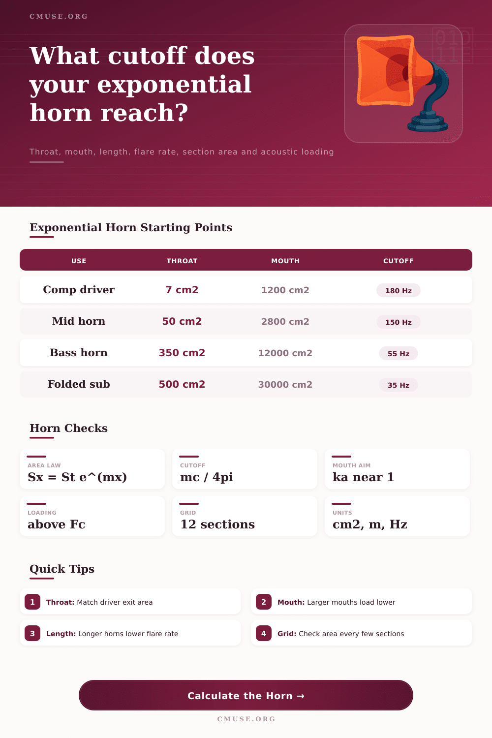
Model an exponential acoustic horn from throat to mouth, then inspect cutoff, flare rate, area growth, mouth loading, and a section grid.
Horn Presets
Inputs
Calculation Breakdown
Section Area Checkpoints
| Path point | Distance | Area | Equivalent diameter | Area ratio |
|---|
Exponential Horn Grid
| Segment | Length position | Area growth | Section area | Build note |
|---|
Acoustic Loading Table
| Frequency | Frequency / Fc | Normalized throat loading | Mouth ka | Comment |
|---|
Design Sensitivity Table
| Change | Flare rate | Cutoff | Mouth area | Comment |
|---|
Horn Building Tips
Building a horn really does involve math. If you’re thinking this is simply a matter of cutting wood in trumpet form, it’s not. It involves the math of how much the area expands from the throat to the mouth. The exponential curve is not arbitrary. In fact, it’s matching the actual path of sound waves, maintaining acoustic impedance matching so the driver see a consistent load. This eliminates reflection. Reflection cause those nasty peaks and dips in frequency response that destroy clarity. That’s all complicated algebra inside the calculator above but let’s take a look at what each one mean acoustically.
So first thing is the throat area. This should of equal the driver’s effective radiating area, minus any loss from adapters or the phase plug. If not, nothing else going forward matter except noise. Most folks think of mouth as simply a wide-open hole but it has an important acoustic role. It should be sized such that air impedance at its exit equals the free air impedance found outside the horn. That way, high frequencies does not reflect back down the horn. This prevents nasty comb-filtering effects in your listening room.
The Math and Science Behind Horn Speakers
That’s where tradeoffs come into play with length. If you have a long horn, you can have that gentle flare rate which drops the cutoff frequency but doesn’t need an absurdly big opening. You want it more like a lazy river and less like a steep waterfall. That is called flare rate. How fast does the cross sectional area increase? Fast enough and you’ll start getting reflections off that side wall. Slow enough and you need a room sized baffle. It shows you exactly where your cutoff frequency hits given those dimensions, this helps you find the sweet spot.
The horn’s efficiency has a hard cutoff known as cutoff frequency. Below this frequency, the horn will no longer behave as a waveguide and will begin to act more like a sealed box. At this point, the driver compliance begin to take over, and you’ll see a quick roll-off in response. That’s not always a bad thing, so long as you’re properly high-passing the signal; however, your midbass will lack that horn-loaded punch at frequencies below the calculated Fc. Before you cut a single piece of wood, you should know this number.
Finally, consider the issue of acoustic loading. Horns are relatively transparent as frequency rises. At very high frequencies, the ratio of mouth size to wavelength matter less. Instead, it is more important that wavefronts is small enough to easily pass through the opening. But in the general area of the cutoff region, the loading from the driver on the horn throat is critical. You can use the calculator to get an idea of how “loaded” the driver feels (normalized) at different frequencies. This should help you anticipate whether your suspension system can handle the load, or if it may be bottomed-out mechanically.
These practical considerations involve real-world constructions that go beyond idealized geometries. Edges scatter sound; corners add diffraction which tend to flatten the response. Folds in a route change the effective length without changing the physical length, which can adds turbulence at every turn. The section area check points in the tool let you see where the horn is widest and design your internal damping/bracing materials appropriatly. The point here is to be transparent; you’re trying to get the listener to hear the source without the enclosure in the way. Properly expanding the air allows the energy from the diaphragm to flow freely into the listening environment. It’s a blend of acoustic theory and physical space.
Begin by knowing the parameters of the driver(s), set the cutoff just under where you want it to go, then follow the geometry. If you do this correctly, the horn won’t sound like its own separate component but more like an extension of the driver itself. This smooth transition is what makes a great design stand out from a good one.