Console Summing Calculator
Estimate stereo mix bus level, summing gain, peak headroom, and the trim move needed before routing stems through a console, summing mixer, or analog mix bus.
Console Sum Results
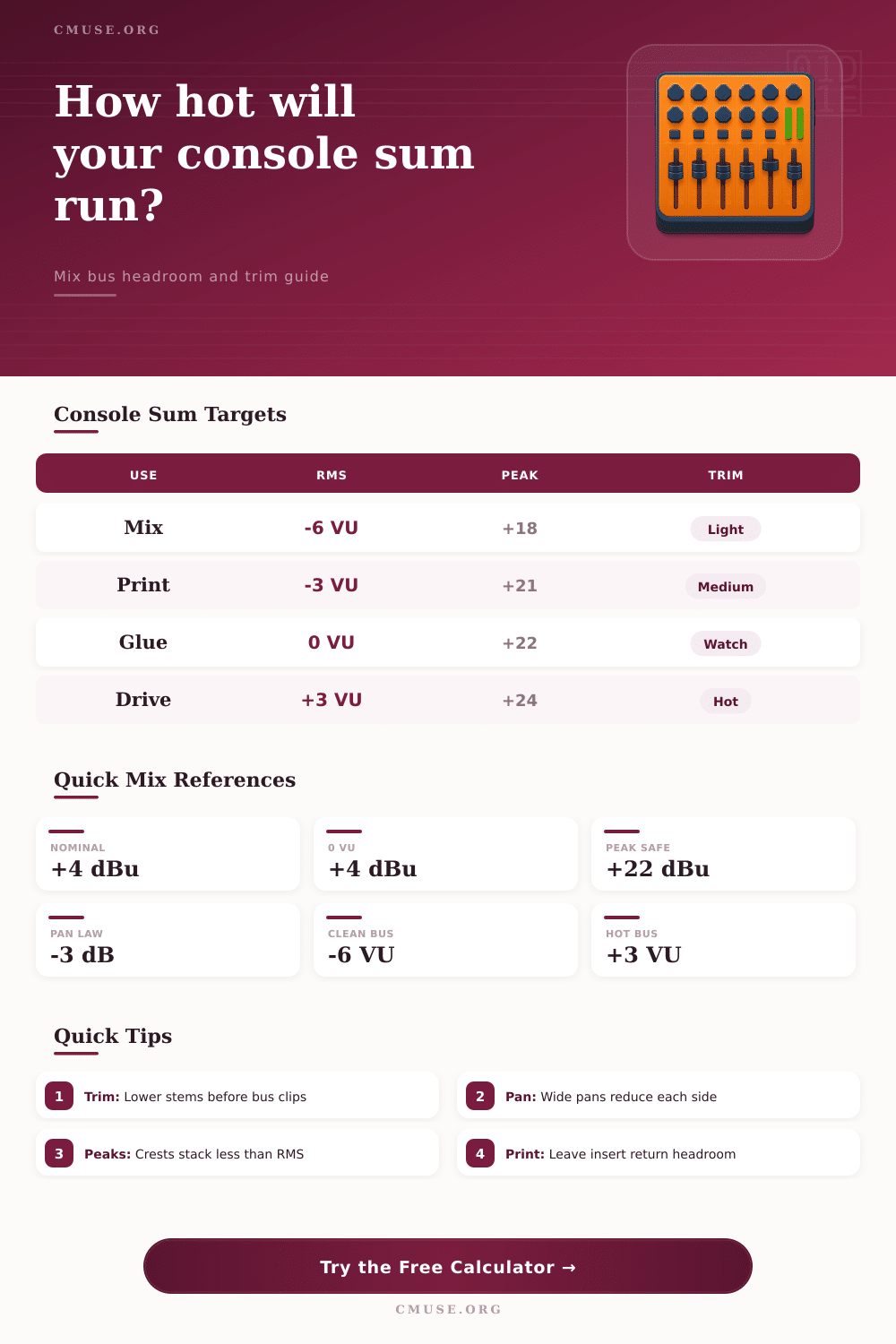
| Bus Condition | VU Around +4 dBu | Approx RMS dBu | Peak Target | Mix Bus Meaning |
|---|---|---|---|---|
| Clean stem print | -6 VU | -2 dBu | +16 to +18 dBu | Open headroom for inserts and later limiting. |
| Normal analog mix | -3 VU | +1 dBu | +18 to +21 dBu | Strong level without leaning hard on the bus amp. |
| Nominal console tone | 0 VU | +4 dBu | +20 to +22 dBu | Classic alignment point for many professional desks. |
| Driven color pass | +3 VU | +7 dBu | +22 to +24 dBu | Use only when the console color is intentional. |
| Clip risk zone | +6 VU or more | +10 dBu | +24 dBu or more | Trim groups, returns, or master insert makeup. |
| Source Relationship | Correlation Setting | 16 Equal Sources | 32 Equal Sources | Use For |
|---|---|---|---|---|
| Loose multitrack | 0.02 | +12.4 dB | +15.4 dB | Drums, guitars, vocals, effects moving independently. |
| Typical pop mix | 0.08 | +14.0 dB | +17.4 dB | Balanced modern production with some layered parts. |
| Layered section | 0.18 | +15.8 dB | +19.6 dB | Doubled guitars, synth stacks, tight percussion loops. |
| Stacked vocals | 0.35 | +18.0 dB | +22.0 dB | Choruses, unison layers, harmony blocks. |
| Near mono stems | 0.60 | +20.2 dB | +24.4 dB | Mono print checks or duplicated stem routing. |
| Topology | Typical Bus Ceiling | Practical Drive | Calculator Offset | Best Use |
|---|---|---|---|---|
| Clean active summing mixer | +26 dBu | -6 to -3 VU | 0 dB | Transparent hybrid routing and recallable stem prints. |
| Large-format inline console | +26 dBu | -3 to 0 VU | +0.5 dB | Full-band mixes with EQ and aux returns on the desk. |
| Transformer-coupled bus | +24 dBu | -3 to +3 VU | +1.2 dB | Color passes where low-mid density is part of the sound. |
| Vintage discrete console | +23 dBu | -6 to 0 VU | +1.5 dB | Characterful mix paths that need more peak caution. |
| Passive summing plus makeup | +24 dBu | -6 to -3 VU | -1 dB | External makeup gain with inserts after the summing node. |
| Broadcast console path | +24 dBu | -3 to 0 VU | +0.8 dB | Program mixes with predictable metering and speech peaks. |
| Mastering-grade line mixer | +28 dBu | -6 to 0 VU | -0.5 dB | Clean stem mastering, alternate mix versions, recalls. |
| Compact project console | +21 dBu | -9 to -3 VU | +2 dB | Smaller desks where internal rails clip earlier. |
| Project | Stem Count | Center Sources | Likely Correlation | Starting Trim |
|---|---|---|---|---|
| Singer-songwriter hybrid mix | 12 to 18 | 4 to 7 | 0.05 to 0.10 | -2 to -4 dB per stem |
| Indie band console pass | 20 to 28 | 7 to 10 | 0.08 to 0.18 | -3 to -6 dB per stem |
| EDM stem mix | 24 to 40 | 8 to 14 | 0.18 to 0.35 | -6 to -9 dB per stem |
| Vocal stack and trackout | 32 to 48 | 18 to 32 | 0.25 to 0.45 | -8 to -12 dB per stem |
| Film or orchestral stem print | 48 to 96 | 10 to 24 | 0.02 to 0.12 | -8 to -14 dB per stem |
Summing occurs when many audio tracks are combined into a single mix bus. Summing can significently increases the signal level. As more tracks are combined, the volume of the mix bus increases.
This clipping of the mix bus can occur as a result of the increase in volume of the mix bus. To understand how much volume will increase from summing together all of the tracks in you project, it is first important to understand how the signals from those tracks relates to each other. The arrangement of the audio tracks within your project will impact the total volume that the mix bus will reach.
How to Stop the Mix Bus from Clipping
For example, tracks that are panned to the center of the stereo field will hit both the left and right channel with its full strength. Thus, these types of tracks will increase the total volume of the mix bus more then tracks that are panned to the sides of the stereo field. The wider that you pan a track, the more the signal from that track is distributed to both the left and right channels.
By distributing the power of a track to both the left and right channels, you can reduce the total volume of the mix bus. Many people overlook the fact that tracks that are panned to the center of the stereo field, such as kick drum or vocals, will contribute to the total volume of the mix bus more than wide tracks. Thus, engineers must monitor these tracks to make sure they dont clip the mix bus.
The correlation between audio tracks will also impact the total volume of the mix bus. The correlation between two tracks indicates the similarity between the two tracks’ waveforms. If the audio tracks that are being mixed together have high correlation to each other, their signals will align with each other over time.
As a result of these highly correlated signals, the total volume of the mix bus will increase much more faster than if it contained only tracks with low correlation to each other. For example, vocal stack will have high correlation with each other, meaning that they will increase the total volume of the mix bus much faster than if they contained only unrelated tracks, such as drums and guitars. The crest factor of the mix bus can help to inform the mastering engineer as to the amount of headroom that will exist on the mix bus for processing insert effects.
Crest factor is the difference between the average signal level (measured in RMS) and the peak signal level of the mix bus. The peaks within a track dont always align with the peaks of other tracks in a project. Because of this fact, tracks with a high crest factor will have more headroom within the mix bus than tracks with a low crest factor.
Thus, engineers must take the crest factor of a mix into account when calculating the amount of headroom that will exist for the mix bus. Gain staging is essential for mix engineers to ensure that there is enough headroom within the mix bus. The digital audio workstation (DAW) should be calibrated to the input levels of the mixing console.
For instance, if the mixing engineer wants to achieve a certain voltage into the mixing console, the engineer will have to adjust the DAW to its output to reach that voltage. The RMS level of each of the stem in the song will need to be measured along with the level of any fader trim adjustments to determine the total volume of the mix bus. A target voltage reading can be modeled into the mix bus’s VU meter.
However, it is essential that engineers always monitor the ceiling of the mix bus so that signals dont clip. Each type of hardware will reach its voltage limit and begin to add distortion to the signal at a different voltage than another type of hardware. For example, a vintage discrete desk may add distortion to the signal at a lower voltage than a clean active mixer.
Additionally, master insert effects, such as equalizers or compressors, will alter the signal level of the mix bus. Passive equalizers will reduce the signal level going into the mix bus. A compressor can increase the signal level as the makeup gain controls on the device are adjusted.
These changes to the signal level must be accounted for in calculating the total headroom of the mix bus. There are a few strategies that can be used to avoid clipping. First, engineers should trim center panned tracks to ensure they do not increase the total volume of the mix bus too much.
Second, effect returns, such as reverb returns, should be offset because they have high peak levels yet low correlation to the other tracks. Third, engineers should monitor the correlation between each track in the mix so that they are aware of tracks that will quickly increase the total volume of the mix bus. Finally, an amount of headroom should always be left after processing inserts are placed into the mix bus.
By gaining an understanding of how to properly stage the gain at every step of the track, and by understanding how track pan positions relates to the total volume of the mix bus, engineers will have headroom that is clean and will not result in the red lights on there meters.