Conical Horn Calculator
Estimate conical horn throat and mouth diameter, axial length, included flare angle, solid angle, low-frequency control, expansion ratio, directivity, and useful geometry sweeps.
Calculation breakdown
| Length change | Length | Included angle | Solid angle | Expansion | Length cutoff |
|---|
| Frequency | Wavelength | Mouth / wavelength | Beamwidth | Directivity Index | Guide |
|---|
| Mouth scale | Mouth diameter | Mouth cutoff | Expansion ratio | Included angle | Use note |
|---|
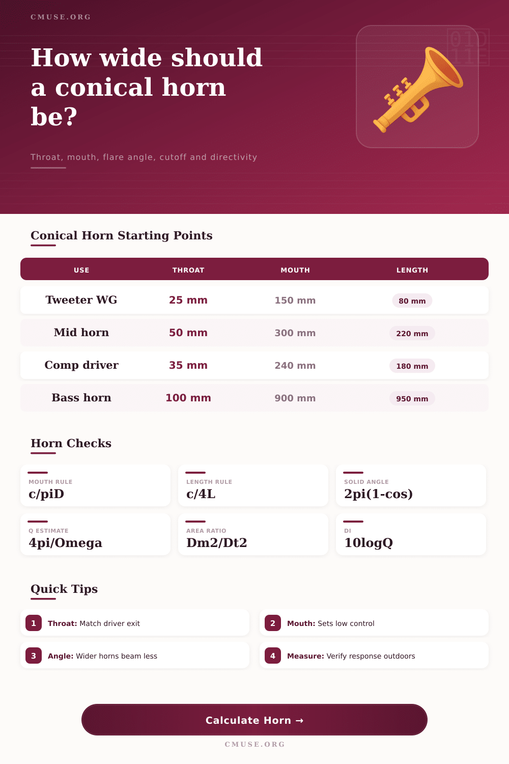
| Preset | Throat | Mouth | Length | Angle | Typical use |
|---|
| Measure | Small / Low | Middle | Large / High | Design meaning |
|---|---|---|---|---|
| Included flare angle | Under 35° | 35° to 75° | Above 75° | Narrow angles increase throw; wide angles trade throw for coverage. |
| Expansion ratio | Under 10:1 | 10:1 to 80:1 | Above 80:1 | Higher ratio usually gives stronger acoustic transformation but a larger package. |
| Mouth diameter / wavelength | Under 0.5 | 0.5 to 1.5 | Above 1.5 | Small mouths lose low-frequency control and large mouths beam at high frequency. |
| Geometric Q | Under 4 | 4 to 12 | Above 12 | Higher Q means more directional energy in the horn axis. |
The geometry is what matters most; there are no tight tolerances for making a horn loader, just geometry control. If you make it conical with smooth tapering (no crazy curves) it works. However, this makes the trade-offs between low-frequency control, directivity, and throw less obvious. To get good loading into driver, you need some expansion but not so much that it flares out too quickly, reflects back, and ruins response. Once you enter your numbers into the calculator it does all the math for you instead of you having to guess if your selected angle is going to narrow the beam or add ripple.
It begins with the throat. Here’s where horn meets the driver. It should have roughly the same diameter as transducer exit of whatever speaker you’re driving. Anything smaller than that creates a bottleneck that will reflect back to cone causing distortion. Anything larger and you lose acoustical loading efficiency, i.e., the driver can’t efficiently drive the air column.
How to Design a Horn Loader
With these three dimensions… Axial length, mouth size and throat. You input them into tool and it solves for the included flare angle. This is the one key geometric variable that makes all the difference. An angle below thirty-five degrees narrows the beam and gives you lots of throw, good if you want something to project a long distance away but not so good when trying to fill small room. Seventy-five degrees and up widens the beam across horizontal plane but loses depth. It also greatly increases potential for high frequencies to beam out of mouth.
Now the horn’s maximum effective range, where it stops controlling driver’s motion, depends on how the horn’s mouth diameter interact with wavelength of the sound. In other words, as the mouth gets smaller it will cut off low frequency earlier, requiring a crossover to shield the driver from flapping around unchecked. Based off some practical rules of thumb, the calculator estimates where this cutoff occur. However, it’s important to understand that how close you can come to the low end relies heavily on enclosure (or box) size and baffle loading. That is, a horn sitting in free space behave different than one tucked in a corner or backed up against solid wall. The tool also lets you choose radiation space. This varies directivity index to match whether you are dealing with a corner load scenario, a half space, or a full space.
The other critical parameter is the expansion ratio, which measures how rapid the horn expands from its throat to its mouth. In general, higher ratios translates into greater efficiency and better low-frequency extension (but require a longer physical length at given flare angle). At less than ten-to-one, you’re basically only guiding the sound; you aren’t really loading it. That’s fine for smooth midrange response, but forget about getting any bass punch. This chart on page spells it out, comparing how different presets balance these parameters for common applications such as vocal PA horns or tweeter waveguides. Compare your custom design with these standard archetypes to determine whether you’re pushing it too far.
Many builders is surprised when their speakers produce a harsh side sound; most don’t realize that directivity is frequency-dependent and can change radicaly. An apparently neutral-sounding mouth on axis at two kilohertz may beam narrowly at five kilohertz if the diameter is large relative to wavelength. At the frequency of your choice, the calculator compares mouth’s diameter to the wavelength and provides an estimate of the shift expressed as a directivity index predicting how much sound will be beamed. That’s important to crossover design: You’d like the horn’s natural beaming to complement, not fight against, your crossover slopes.
All that said, there will never be an online calculator that truly emulates real world differences such as material stiffness, acoustic loss, or variations in driver compliance. It’s a great starting place, purely geometrically speaking, but ultimately what matters most are measurements and your ears. You should of used more measurements. To identify phase problems that aren’t predictable by geometry alone, go measure outside or in an anechoic chamber and make sure everything sounds right.
Begin with the math, construct your prototype, and really listen. That cone shape is only part of the picture; how well those angles aligns with your drivers and your particular space will determine the sound they produce.