Bandpass Subwoofer Box Calculator
Size the rear chamber, front chamber, and port so your bandpass build fits the driver, the tuning target, and the cabinet footprint.
📦 Real Bandpass Presets
⚙ Setup
📊 Bandpass Spec Grid
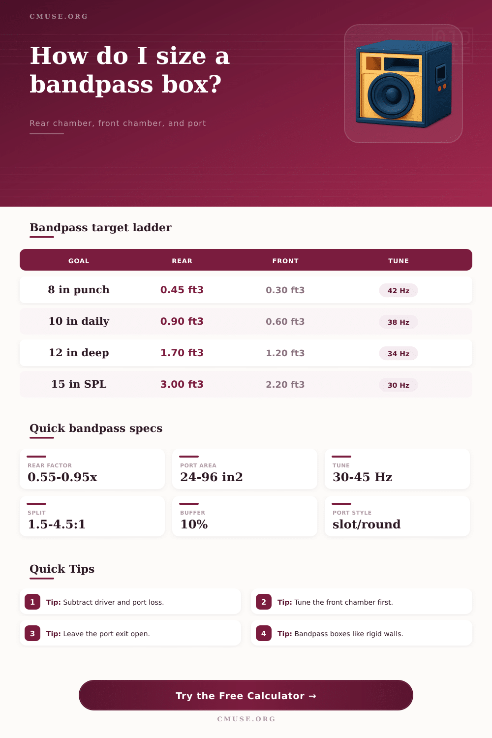
📒 Alignment Reference
| Goal | Rear:Front | Tune window | Use case |
|---|---|---|---|
| Punch | 1:0.55 | 38-48 Hz | Hard hit |
| Balanced | 1:0.70 | 34-44 Hz | Daily mix |
| Deep | 1:0.84 | 30-40 Hz | Lower end |
| SPL | 1:0.95 | 40-54 Hz | Peak output |
| Driver | Vas band | Qts band | Typical note |
|---|---|---|---|
| 8 in | 0.4-1.0 ft3 | 0.35-0.45 | Compact |
| 10 in | 0.8-1.8 ft3 | 0.38-0.48 | Street |
| 12 in | 1.8-4.0 ft3 | 0.40-0.52 | Daily |
| 15 in | 4.0-8.0 ft3 | 0.42-0.55 | Low end |
| Port style | Area / driver | Front tune | Bandpass use |
|---|---|---|---|
| Slot | 30-45 in2 | 36-44 Hz | Punch |
| Round | 24-36 in2 | 34-42 Hz | Clean |
| Flared | 28-40 in2 | 32-40 Hz | Daily |
| Dual slot | 40-70 in2 | 38-50 Hz | Loud |
| Shape | Best for | Area formula | Note |
|---|---|---|---|
| Rectangle | Trunk builds | L x W | Easy to frame |
| Circle | Round shell | pi r2 | Compact curve |
| Triangle | Wedge backs | 0.5 b x h | Seatback fit |
| Custom | Odd panels | Direct area | Irregular face |
💬 Bandpass Tips
A bandpass subwoofer enclosure consist of two separate internal chamber. Each of these internal chambers are referred to as either the rear chamber or the front chamber. The rear chamber is formed of the area in which the backwave of the subwoofer driver is contain.
The rear chamber dictate the compliance of the subwoofer driver. The front chamber is the chamber within which the port is contain, and it dictates the frequency range of the subwoofer enclosure. If the rear chamber is too large for the subwoofer driver, the subwoofer enclosure will lack control in the low frequencies.
Building a bandpass subwoofer box
If the rear chamber is too small for the subwoofer driver, the subwoofer enclosure may lack depth in its low frequency sound output. If the front chamber is too small in relation to the area of the port, the subwoofer enclosure will have a narrower range of low frequency sound output. If the front chamber is too large in relation to the area of the port, the subwoofer enclosure may lose output pressure.
In order to calculate the size of the rear and front chambers, you must calculate the parameters of the subwoofer driver. For instance, many people uses the Vas value for the subwoofer driver in order to determine the size of the rear chamber. Vas is the value of the compliance of the driver.
For instance, individuals that desire a subwoofer enclosure that produce a punchier (rather than deeper) sound may opt for the smaller rear chamber. Individuals that desire a deeper sounding subwoofer may opt for the larger rear chamber. The front chamber must be tune to a specific frequency, which the length of the port and the area of the port determine.
For example, a subwoofer enclosure that is to be use daily may have a front chamber with 70% of the volume of the rear chamber. However, a subwoofer enclosure that is to frequently produce high sound pressure levels may have a front chamber with nearly the same size than the rear chamber. In addition to the parameters of the subwoofer driver, you should consider the physical dimensions of the area in which the subwoofer enclosure is to be place.
The physical dimensions of the trunk or seatback area can limit the size of the subwoofer enclosure that is built. For instance, subtracting the volume of the subwoofer driver, the volume of the bracing, and the volume of the port from the total volume of the subwoofer enclosure can calculate the total internal volume of the subwoofer enclosure. Additionally, 10% of the total calculated volume can be subtracted from the total internal volume to account for the thickness of the bracing panels and the sound output components of the subwoofer enclosure.
Finally, the material from which the subwoofer enclosure is construct is also important. For instance, you can use materials like birch plywood to construct the subwoofer enclosure, as well as thick baffle. Regardless of the material that is selected, rigid bracing must be use.
The air pressure within a bandpass filter subwoofer enclosure is very high; high air pressures can cause the sides of the subwoofer enclosure to flex. If the sides of the enclosure flex, the subwoofer enclosure will lose efficiency and the sound may become distortedly. The port that is placed within the front chamber is also important.
Ports can be slot or round ports. Regardless of the type of port that is use, the area of the port should be large enough to allow the air to move through the subwoofer enclosure at sufficient rates to allow for efficient sound production, but not so large as to create air turbulence within the enclosure. Air turbulence within the subwoofer enclosure create a chuffing noise that is not desire when high quality sound is to be produce from the subwoofer enclosure.
The length of the port must be calculate with the desired tuning frequency of the subwoofer enclosure; the longer the port, the lower tuning frequency of the subwoofer enclosure. Finally, after the subwoofer enclosure has been construct, it should be test. For example, tone sweeps can be played through the enclosure to assess the frequency response of the subwoofer enclosure.
If the frequency response is not even within the low frequencies of the subwoofer enclosure, adjustment can be made to the subwoofer enclosure before it is complete. Thus, successful construction of a bandpass subwoofer enclosure require an understanding of the math behind its construction, the material necessary to build it, and the volumes of each of its chambers.