Audio Transformer Design Calculator
Size turns ratio, core area, inductance, and flux density for mic, line, interstage, and output audio transformers.
M6 Steel
1.55 T
Strong LF headroom for EI output stages and line transformers
Silicon Steel
1.40 T
Balanced bandwidth and practical winding size for general use
80% Nickel
0.80 T
High permeability for small signal and mic transformers
Ferrite
0.35 T
Best when higher frequency response matters more than LF swing
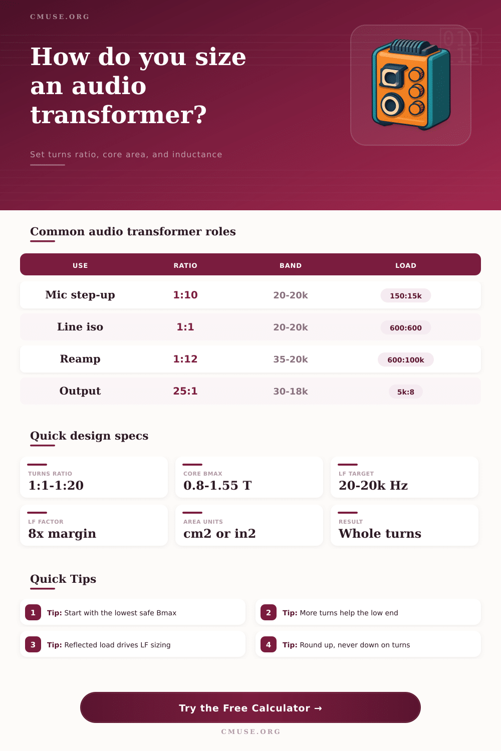
| Role | Typical ratio | Low end | Core note |
|---|---|---|---|
| Mic step-up | 1:10 | 20 Hz | Nickel core |
| Line isolation | 1:1 | 20 Hz | Steel core |
| Reamp box | 1:12 | 35 Hz | Steel core |
| Tube output | 25:1 | 30 Hz | Large EI |
| Interstage | 1:1 | 10 Hz | Nickel core |
| Material | Bmax | Mu | Best use |
|---|---|---|---|
| M6 grain steel | 1.55 T | High | Power and output |
| Silicon steel | 1.40 T | High | General audio |
| 80% nickel | 0.80 T | Very high | Mic and line |
| Ferrite | 0.35 T | High | HF coupling |
| Amorphous | 1.20 T | High | Low loss EI |
When winding a microphone transformer, you may find that the low end of the frequency response rolls off at 50 Hz. This occurs due to an undersized area of the transformer’s magnetic core. The three main element of a transformer are flux density, reactance, and reflected impedance.
These three factors directly impact the frequency response of the transformer. The inductance of the primary at the lowest end of the audio band present the challenge for transformer design. At 20 Hz, the primary inductance will determine the reactance of the primary.
Fixing Low Bass in Microphone Transformers
The reactance of the primary should be eight times greater than the source impedance of the capsule that radiates the sound. Otherwise, the bass note will sag under the load. The area of the magnetic core determine the inductance of the primary coil.
The flux density limits the amount of turn per volt. Adding more turns will increase the inductance but will crowd the winding. The materials used for the magnetic core will also impact the balance of the transformer.
Grain-oriented steel, like M6, can handle 1.55 tesla before it saturate. The output stages of a transformer will use up this headroom in the magnetic material. Nickel alloys saturate at 0.8 tesla but have a high permeability that makes them suitable for use in small microphone transformers with a low signal.
First, you will pick the geometry of the core. Rectangular stacks use EI laminations as common designs for power audio applications. Triangular and circular core will work for toroids and other custom bobbin designs.
Increasing the depth of the magnetic stacks will increase the core area but will also increase the size of the winding. Thus, you are trading the size of the transformer for low-frequency performance. Adding overage buffer will allow the magnetic material to not saturate with the signal peaks.
Adding 10 or 20 percent to the winding counts will allow for this overage buffer. The next critical factor to consider is impedance matching. Using a 1:10 microphone transformer will give the 15k secondary load a reflected load of 150 ohms on the primary because reflected impedance is based off the load squared.
Using an impedance calculator will allow you to balance the source impedance of the capsule against the reflected load of the primary. This will give you a better understanding of the primary inductance that you need to target for the transformer. Voltage swing are another factor to consider when designing the primary coil of a transformer.
If the primary voltage is 1V RMS, the B-field must not exceed the limits of the magnetic materials across the audio frequency range. The power level of the signal will tell you the current density in the voice coil. The current density will allow you to select the wire gauges for the primary and secondary to prevent them from melting with 3 amps per square millimeter.
Using presets can significantly speed up the process of transformer design. For instance, step-up transformer for microphones will use nickel powder cores and shallow magnetic stacks. Using a 1:100 ratio for line isolators will work with silicon steel cores and a 1:1 ratio of the primary and secondary coils to provide an excellent frequency response at 20 Hz.
For tube outputs, a 25:1 ratio or higher will be used. The higher the ratio, the larger the magnetic core such as M6 to handle 20V without compression of the audio signal. Reamp boxes may use a 1:12 ratio for guitar pedals, but a 1:12 ratio will sacrifice some of the bass punch for a brighter attack at 35 Hz.
Each preset use realistic impedances and voltages to start your design. Builds will always reveal issues that formulas do not reveal. The inductance will control the low end of your transformer, but the inter-winding capacitance will control the treble.
You can use sectional windings or mu-metal shields to fight against the inter-winding capacitance. The coupling will affect the presence of leakage inductance, which will affect the ringing of the transient signal unless the windings are layered proper. Excessive current density can cook the insulation between the transformer laminations.
High-mu magnetic cores will have air gaps to linearize the magnetic field in the presence of DC bias from the single-ended amplifier stages. Using a low number of turns will try to save space on the transformer but will starve the low end of your frequency response. More turns will help the low end of your transformer, assuming that you are within the winding limits.
Another mistake is ignoring the reflected load from the transformer secondary. If the reflected load is not matched with the primary, the efficiency will drop as the transformer will act as an open or short circuit. The source impedance sets the lower limit of the reflected load, but the squared ratio will dominate the reflected load.
Using ferrite core material for audio transformers will fail in the low-end frequencies. Ferrite cores will work well for audio frequencies above 1kHz but will require massive magnetic areas to operate at frequencies below 100Hz due to the Bmax limit of 0.35T for ferrite materials. The following table will show the different magnetic materials and their properties.
M6 metal is excellent for power transformers. Silicon steel will offer a good balance between bandwidth and size. Nickel metal is great for small signal transformers.
Amorphous metal will have reduced hysteresis loss to give a cleaner sound but will cost more. Ferrite core materials are suitable for high-frequency switchers but will not work well for bass-heavy audio line levels. Higher Bmax for the core materials will allow your transformer to have fewer turn.
Fewer turns will allow for smaller magnetic cores. However, a higher Bmax will increase the chance of saturation in dynamic signals. Current density will tell you what gauge of wire to use for your primary winding.
Using 3 A/mm2 of current density, a 100mA primary will use AWG 28 wire to allow headroom for the 20% peak current in your signal. You should always round up the number of turns for your transformer windings and never round down the number of turn. When you wind your transformer, you should test it on a bench using a sweep signal generator.
If the low frequency response is weak with your transformer, you will have to stack the transformer deeper or change the magnetic materials used to make the transformer. The output of a properly designed transformer will feature the number of turn for the primary and secondary windings, the ratio of the two, and the minimum inductance for the primary or secondary winding. The breakdown of a well-designed transformer will feature the core volume, the actual B-field within the core, and the gauge of wire to use for the windings.
Make sure the flux density within the core is under 80% of the Bmax for music transformers. Also, make sure that the inductance is eight times the impedance for the primary winding so that the bass frequencies are felt properly. By keeping the area of the magnetic core within the same proportion as the required inductance, your transformer will function correctly.