Audio Notch Filter Calculator
Design a notch filter for hum, buzz, resonant peaks, or feedback using twin-T, RLC, or DSP biquad math.
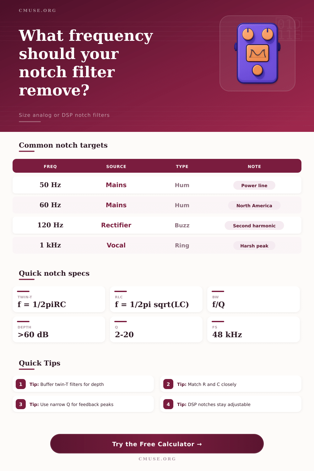
🎧 Preset Notch Targets
⚙ Filter Setup
📊 Component Quick Spec
📖 Reference Tables
| Frequency | Typical source | Use case | Note |
|---|---|---|---|
| 50 Hz | Mains hum | Studio hum | Power line region |
| 60 Hz | Mains hum | Live rack noise | North American mains |
| 120 Hz | Rectifier buzz | Power supply ripple | Second harmonic |
| 180 Hz | Room boom | Low end cleanup | Often room related |
| 400 Hz | Snare ring | Drum cleanup | Useful on resonant shells |
| 900 Hz | Vocal honk | Speech smoothing | Nasal resonance zone |
| 2.5 kHz | Feedback peak | Monitor control | Critical hearing area |
| 4 kHz | Harsh tone | Instrument tame | Bright edge reduction |
| Mode | Start point | Formula | Use |
|---|---|---|---|
| Twin-T 50 Hz | 10 k + 0.318 uF | f = 1/2piRC | Power hum |
| Twin-T 60 Hz | 10 k + 0.265 uF | f = 1/2piRC | Studio hum |
| Twin-T 120 Hz | 8.2 k + 0.162 uF | f = 1/2piRC | Ripple buzz |
| RLC 400 Hz | 10 mH + 15 uF | f = 1/2pi sqrt(LC) | Shell ring |
| RLC 1 kHz | 3.3 mH + 7.2 uF | f = 1/2pi sqrt(LC) | Peak trim |
| DSP 2.5 kHz | Fs 48 kHz | b0,b1,b2,a1,a2 | Monitor notch |
📝 Biquad Coefficients
How to use the results
Select a preset or enter your own values, then compare the analog and DSP outputs. Twin-T favors simplicity, RLC favors tuning, and DSP favors adjustability.
- Twin-T rejection improves with close R/C matching.
- RLC notches narrow as Q rises.
- DSP notches can be retuned without swapping parts.
- Source and load impedance affect analog depth.
💡 Practical Tips
A notch filter is used to remove unwanted frequencies from an audio signal. Unwanted frequencies may include feedback whines or hums from power lines. A notch filter allows a person to remove one specific frequency from an audio signal while leaving the other frequencies alone.
There are two main control on a notch filter: the center frequency and the Q factor. The center frequency control set the location of the notch on the audio signal. The Q factor control dictates the width of the notch.
Notch Filter Basics
A notch filter with a high Q factor will create a very narrow notch and is useful in removing a single, specific feedback tone. A notch filter with a low Q factor will create a wide notch and is useful in remove a broad range of frequencies, such as hum from a power line. Using a Q factor that is too wide may cause the notch filter to remove good frequencies from the audio signal.
Using a Q factor that is too narrow may cause the notch filter to not remove the unwanted frequency from the audio signal if the unwanted frequency shifts even slight from the original frequency. Notch filters can be analog or digital. Analog notch filters use resistors and capacitors to create a notch filter.
One example of an analog notch filter is the twin T network. The twin T network use a specific ratio of resistors and capacitors to create a notch filter. To calculate the frequency of the twin T network, you can use the following equation: frequency = 1 / 2 times pi times resistance times capacitance.
The source impedance of the audio signal being filtered impact the twin T network. If the source impedance of the signal is too high, it will load the twin T network and create a shallow notch filter. To avoid this issue, the signal should keep the source impedance low.
Another type of analog notch filter is the RLC notch filter. This type of notch filter use inductors and capacitors to create the notch filter. This notch filter is useful for removing midrange rings from an audio signal.
However, because RLC notch filters use inductors, they may increase the cost and size of the notch filter. Digital notch filters are implemented using DSP, or digital signal processing. Digital notch filters use biquad filters.
Biquad filters is second-order IIR (infinite impulse response) filters. Digital notch filters run in software or on chips. To use a digital notch filter, a person must provide the unwanted frequency, the Q factor, and the sample rate to the digital notch filter.
The digital notch filter will calculate the coefficients b0, b1, b2, a1, and a2 that will allow it to function as a notch filter. Digital notch filters allow for infinite adjustments to a notch filter without having to solder on new components to an audio device. A notch filter has two main specifications: the bandwidth of the notch and the rejection depth.
The bandwidth of the notch filter is the width of the notch of the filter. To calculate the bandwidth of a notch filter, divide the frequency by the Q factor. For example, if the bandwidth of the unwanted frequency is 60 hertz with a Q factor of 10, the bandwidth of the notch filter is 6 hertz.
The rejection depth of a notch filter is the amount that the notch filter will reduce the volume of the unwanted frequency. A rejection depth of 60 decibels (dB) is often targeted for notch filters. However, the rejection depth may be less than targeted due to component tolerances or signal loading.
If the rejection depth of a notch filter is less than 30 dB, the components of the notch filter may need to have tighter tolerances or a buffer may need to be placed into the signal. Notch filters often come with presets for the frequencies that are most commonly problematic in audio signals. In addition to using the presets of a notch filter, a person can use a sweep tone or a spectrum analyzer to measure the actual problem with the audio signal.
Common problems include 50 hertz for European mains hum, 120 hertz for rectifier buzz, 180 hertz for room boom, and 1.6 kilohertz for instrument rings. To ensure the notch filter is working correctly, the notch filter should be tested against the original signal. By testing the notch filter, a person can be sure that it will remove the unwanted frequency from the audio signal without damaging the tone of the audio signal.