Audio Bandpass Filter Calculator
Design RC, RLC, or digital bandpass filters for vocals, drums, bass, synths, and monitors with Center Frequency, Q, and Bandwidth math.
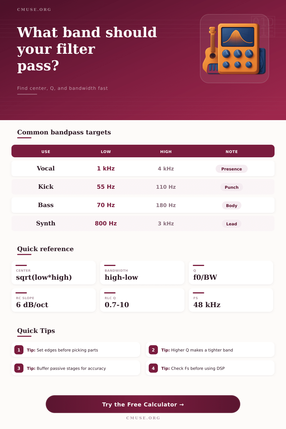
🎧 Bandpass Presets
⚙ Filter Setup
📊 Bandpass Spec Grid
📖 Reference Tables
| Frequency | Typical source | Use case | Note |
|---|---|---|---|
| 50 Hz | Mains hum | Studio hum | Power line region |
| 60 Hz | Mains hum | Live rack noise | North American mains |
| 120 Hz | Rectifier buzz | Power supply ripple | Second harmonic |
| 180 Hz | Room boom | Low end cleanup | Often room related |
| 400 Hz | Snare ring | Drum cleanup | Useful on resonant shells |
| 900 Hz | Vocal honk | Speech smoothing | Nasal resonance zone |
| 2.5 kHz | Feedback peak | Monitor control | Critical hearing area |
| 4 kHz | Harsh tone | Instrument tame | Bright edge reduction |
| Mode | Start point | Formula | Use |
|---|---|---|---|
| RC 50 Hz | 10 k + 0.318 uF | f = 1/2piRC | Power hum |
| RC 60 Hz | 10 k + 0.265 uF | f = 1/2piRC | Studio hum |
| RC 120 Hz | 8.2 k + 0.162 uF | f = 1/2piRC | Ripple buzz |
| RLC 400 Hz | 10 mH + 15 uF | f = 1/2pi sqrt(LC) | Shell ring |
| RLC 1 kHz | 3.3 mH + 7.2 uF | f = 1/2pi sqrt(LC) | Peak trim |
| DSP 2.5 kHz | Fs 48 kHz | b0,b1,b2,a1,a2 | Monitor bandpass |
📝 Biquad Coefficients
How the math is read
Select a preset or enter your own values, then compare the analog and DSP outputs. RC favors simplicity, RLC favors tuning, and DSP favors adjustability.
- RC rejection improves with close R/C matching.
- Series RLC bandpasses narrow as Q rises.
- DSP bandpasses can be retuned without swapping parts.
- Source and load impedance affect analog depth.
💡 Practical Tips
A bandpass filter is an tool that allows for a specific range of frequencies to pass through a circuit, but reduces the volume of the frequencies outside of that specific range. A bandpass filter is different from a high pass filter in that a high-pass filter will remove low frequencies from a signal, but a bandpass filter will remove both low and high frequencies. Similary, a bandpass filter is also different from a low-pass filter in that a low-pass filter will remove high frequencies from a signal, but a bandpass filter will remove both high and low frequencies from the signal.
Overall, a bandpass filter creates a window of sound that allows for only specific frequencies to pass through, and it can be moved to different parts of the sound spectrum. A bandpass filter is defined by three main characteristics: the center frequency, the bandwidth, and the Q factor. The center frequency is the frequency that is located in the middle of the bandpass filter window, and it is the frequency at which the bandpass filter produces the highest response to the frequencies passing through the filter.
What is a bandpass filter?
The bandwidth is the width of the bandpass filter window, and it is measured at the points at which the strength of the signal drop to 70.7% of the maximum strength of the signal. The Q factor, or quality factor, of a bandpass filter is a value that determines whether the bandpass filter have a narrow or wide window of allowed frequencies. High values of the Q factor will result in a narrow bandpass filter window, which is useful for removing a single frequency from a signal.
Low values of the Q factor will result in a wide bandpass filter window, which is useful for removing a range of noises from a signal. The relationship between the Q factor and the bandwidth of a bandpass filter can be determined using mathematical formulas. For instance, if the center frequency of a bandpass filter is 1 kHz and the Q factor is 10, the bandwidth will be 100 Hz.
If the Q factor is increased to 20, the bandwidth will decrease to 50 Hz. Thus, higher values of the Q factor will lead to a smaller bandwidth. It is important to note, however, that many analog bandpass filters have components with tolerances to there specification.
These component shifts can impact the center frequency of the bandpass filter, preventing it from removing the desired frequencies from the signal. There are several types of circuits that can be used to form a bandpass filter. For instance, RC networks can be used to form a bandpass filter, as it use both resistors and capacitors.
An RC network can be formed by combining a high-pass filter with a low-pass filter. Another type of circuit is the RLC network, which use resistors, inductors, and capacitors. Because the circuit uses inductors, the signal can resonate at the specific frequency created by that circuit.
Another type of bandpass filter is the digital biquad filter, which is used in digital signal processing. Digital biquad filters use coefficients in a mathematical calculation to create the bandpass filter within a computer or other digital processor. In order to effective use a bandpass filter, it is important to consider the impedance of the filter.
High values of source impedance can negatively impact the performance of the bandpass filter, so it is important to ensure that the source impedance is less than 1 kOhm. Similarly, if the load impedance is too low, it can negatively impact the bandpass filter. Thus, it is important to ensure that the load impedance is more than 10 kOhm.
One way to counteract the negative impact of impedance on a bandpass filter is to add a buffer stage to the signal. For example, an operational amplifier can be added to the circuit to prevent the load impedance from changing the center frequency of the signal or it’s bandwidth. In order to find the proper settings for a bandpass filter, one way is to use a frequency sweep.
Using a frequency sweep, a technician can play a tone through the signal through a range of frequencies, allowing the technician to listen for the frequency that causes the problem to that signal. Once a technician can find that problematic frequency, they can set it to the center frequency for the bandpass filter. Additionally, the technician can adjust the Q factor for the filter to determine whether only a narrow or wide range of frequencies should be removed from the signal.
After adjusting the settings, the technician should of tested the performance of the bandpass filter with a frequency sweep, as the frequencies create by the bandpass filter can deceive the human ear.