AM Modulation Calculator
Calculate modulation index, carrier power, sideband power, envelope depth, and AM bandwidth from carrier and modulating signal values.
🎛AM scenario presets
📻Carrier, modulator, and load inputs
AM modulation results
📊Live AM specification grid
📐AM formulas used
| Quantity | Formula | Meaning | Notes |
|---|---|---|---|
| Modulation index | m = Vm / Vc | Depth of amplitude change | Keep 0 to 1 for normal AM |
| Lower sideband | fLSB = fc - fm | Difference frequency | Shown in kHz |
| Upper sideband | fUSB = fc + fm | Sum frequency | Shown in kHz |
| Bandwidth | BW = 2 × fm | Total AM channel width | For single highest modulating tone |
| Carrier power | Pc = Vc,rms² / R | Unmodulated carrier power | Vc,rms = Vc,peak / 1.414 |
| Each sideband power | PSB = Pc × m² / 4 | Power in LSB or USB | Both sidebands are equal |
| Total power | Pt = Pc × (1 + m² / 2) | Carrier plus both sidebands | Full carrier AM |
| Efficiency | eta = (m² / 2) / (1 + m² / 2) | Useful sideband power share | Max is 33.3% at m = 1 |
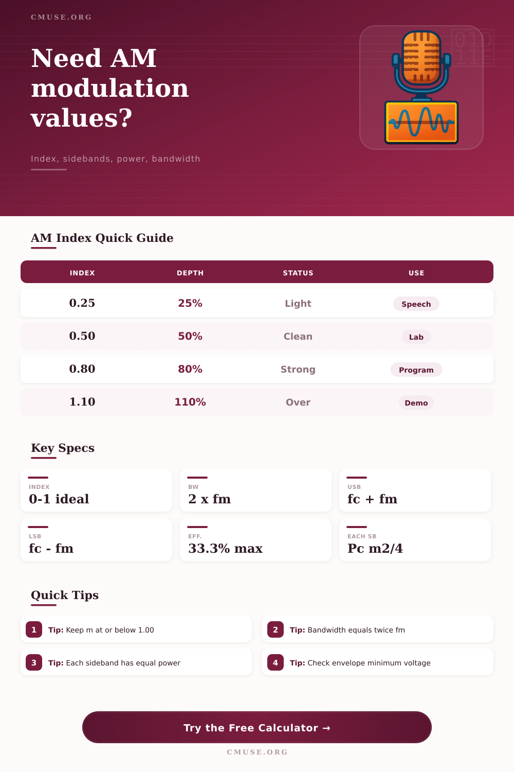
🎚Modulation index reference
| Index m | Depth | Envelope Minimum | Practical Read |
|---|---|---|---|
| 0.10 to 0.30 | 10% to 30% | 70% to 90% of Vc | Light modulation, low sideband power |
| 0.40 to 0.60 | 40% to 60% | 40% to 60% of Vc | Clean teaching and bench examples |
| 0.70 to 0.90 | 70% to 90% | 10% to 30% of Vc | Strong AM envelope without crossing |
| 1.00 | 100% | 0% of Vc | Maximum ideal full-carrier AM depth |
| Above 1.00 | Above 100% | Negative crossing | Overmodulated envelope distortion |
📡Preset comparison table
| Preset | Carrier fc | Modulating fm | Index Target |
|---|---|---|---|
| Broadcast Speech | 1000 kHz | 3.0 kHz | 0.30 |
| Broadcast Music | 1000 kHz | 5.0 kHz | 0.65 |
| 455 kHz Lab IF | 455 kHz | 1.0 kHz | 0.50 |
| Ham Voice AM | 7200 kHz | 2.7 kHz | 0.70 |
| Wide Program Audio | 1500 kHz | 7.5 kHz | 0.75 |
💻Sideband and power examples
| m | Total Power Factor | Each Sideband Factor | Efficiency |
|---|---|---|---|
| 0.25 | 1.031 × Pc | 0.0156 × Pc | 3.0% |
| 0.50 | 1.125 × Pc | 0.0625 × Pc | 11.1% |
| 0.75 | 1.281 × Pc | 0.1406 × Pc | 22.0% |
| 1.00 | 1.500 × Pc | 0.2500 × Pc | 33.3% |
💡Calculation tips
Amplitude modulation are used in many radio systems because amplitude modulation is so easy to generate and amplitude modulation is so easy to receive. To perform amplitude modulation, one takes a steady carrier wave and changes the strength of that wave over time according to a lower frequency signal. That lower frequency signal could be a voice (or a test tone) or it could be music and speech.
The result of amplitude modulation is a wave whose peaks and troughs contain an information from the original signal. To perform amplitude modulation properly, one must understand the depth of the variations of that signal, the extra power require to transmit that signal, and the width of the spectrum of that signal. The modulation index determine the distance that the amplitude of the carrier signal is modulated.
How AM Works and Why Modulation Index Matters
The modulation index is the ratio of the peak voltage of the modulating signal to the peak voltage of the carrier signal. If the modulation index is set to remain under a value of one, the signal will remain in conventional AM. Should the modulation index be increased past a value of one, the envelope of the signal will fold back onto it’s self.
This folding of the signal will result in distortion of the signal that the receiver picks up, and the signal will become wider than necessary for the information it is transmitting. The information from the amplitude modulated signal exist within the sidebands of that signal. When the carrier wave is modulated, new frequencies appears both above and below the frequency of the carrier wave.
These new frequencies are referred to as sidebands. The sidebands are spaced at regular intervals from the carrier wave equal to the frequency of the signal being amplitude modulated. The total bandwidth of the signal is twice the frequency of the highest frequency component in the modulating signal.
This is one of the reasons that AM channels are spaced 10 kHz apart from one another in the AM radio band, and why narrowband voice channel are 6 kHz or less in width. Power accounting for amplitude modulated signals is just as important as the accounting of the frequency of the signal. For a carrier signal without modulation, the RMS voltage of the signal divided by the resistance of the load establishes the power radiated by the signal.
The final amplifier stage draws the power of each sideband. At 100% modulation, the total power of the two sidebands is 50% of the power of the carrier signal. Thus, 50% of the total power radiated by the transmitter is the signal of interest; the other 50% of the total power is the carrier signal that contains no information.
This explains why single sideband modulation became of interest to radio operators performing long distance communications. The calculator included here will calculate the modulation index, the sideband frequencies, the total and sideband power radiated by an AM transmitter, the limits of the envelope of the signal, and the efficiency of that AM transmitter. The calculator also considers whether the signal is a single tone, voice, program, or IF signal.
The formulas within the calculator are instantaneous; changing the modulating frequency will alter the bandwidth of the signal, for instance and increasing the modulation index will increase the sideband power and efficiency (up to the envelope limit of the transmitter). Real AM transmitters often include additional complication beyond the ideal AM signal. For instance, the linearity of the amplifier stages will impact the quality of the modulated signal.
The amplifier may be linear at 60% modulation, for instance, but not at 90% modulation. The distortion created at 90% modulation will be similar to the distortion created in a solid state amplifier stage that is overdriven. The calculated minimum envelope voltage can be compared to the oscilloscope display of the RF envelope; examining the RF envelope is the best means of verifying that the calculations of the AM signal are accurate.
In addition to non-ideal behavior of radio transmitters, other factor to consider are the effect of temperature of components drift. The amplitude of the carrier signal can change with the supply voltage to the transmitter, and the amplitude of a carrier signal can change as the tubes within a transmitter age. Both of these factors will alter the effective modulation index of the signal.
Thus, when setting the transmitter to a certain modulation index with a function generator and tone generator, there will be a slight headstart in the modulation depth that is established so that aging or drift of the signal does not result in overmodulation of the signal. The tables within the reference material included in this article can show the same relationships between variables as the tables within the article. One table show the efficiency of the signal as a function of the depth of modulation of the signal.
A second table shows the minimum envelope voltage of a signal as a function of the modulation index of the signal. A third table shows the preset values for the depth of modulation for speech, music, and IF signals. These tables can be used to quickly verify calculations before committing any hardware to transmitting the signal, or before filing a request for frequency coordination.
The goal in transmitting an amplitude modulated signal is not to reach the maximum theoretical efficiency. The goal is to provide a clean signal within the channel that is allocated to the station, to provide a clean signal that sounds natural, and to avoid creating complaints from adjacent operators. The modulation index, the sidebands of the signal, and the power of that signal are the parameters that allow one to determine whether the signal has achieved these goals.
Once one has established the modulation index, the placement of the sidebands, and the power of the signal, one can begin to match the transmitter, the antenna, and the audio signal to the calculated limit of the system.