All Pass Filter Calculator
Calculate phase rotation, group delay, analog RC values, second-order Q behavior, digital all-pass coefficients, and wet/dry summing for audio phase design.
🎛 Quick All-Pass Presets
📐 All-Pass Inputs
📊 All-Pass Spec Grid
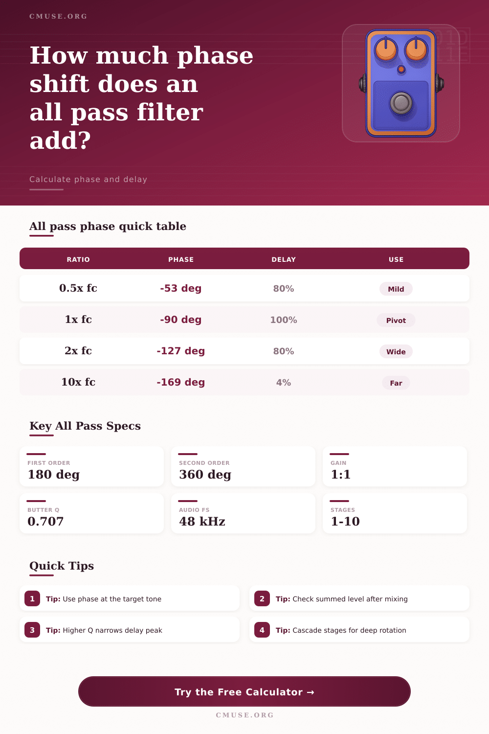
📘 Phase and Delay Reference
| Frequency Ratio | 1st-Order Phase | 1st-Order Delay | Practical Meaning |
|---|---|---|---|
| 0.10 x pivot | -11.4° | 20% of peak delay | Far below pivot, nearly dry phase |
| 0.50 x pivot | -53.1° | 80% of peak delay | Audible rotation before center |
| 1.00 x pivot | -90.0° | 100% of peak delay | Main alignment reference point |
| 2.00 x pivot | -126.9° | 80% of peak delay | Rotation continues above pivot |
| 10.0 x pivot | -168.6° | 20% of peak delay | Approaches inverted phase |
⚙ Topology Comparison
| All-Pass Type | Phase Range | Main Control | Audio Use |
|---|---|---|---|
| First-order analog RC | 0° to -180° | RC pivot frequency | Pedal phasers, simple phase trim, crossover nudge |
| Cascaded first-order | 0° to -180° per stage | Stage count and sweep | Classic multi-stage phaser sound and broad rotation |
| Second-order analog | 0° to -360° | Center frequency and Q | Narrower phase correction around a band |
| Digital first-order | 0° to -180° | Coefficient a | Stable delay-free phase work inside DSP |
| Digital biquad all-pass | 0° to -360° | Frequency, Q, and sample rate | Speaker processing, reverbs, decorrelation, phase matching |
🔧 Analog RC Value Reference
| Pivot Frequency | With 10 nF | With 22 nF | With 100 nF |
|---|---|---|---|
| 90 Hz | 176.8 kΩ | 80.4 kΩ | 17.7 kΩ |
| 150 Hz | 106.1 kΩ | 48.2 kΩ | 10.6 kΩ |
| 700 Hz | 22.7 kΩ | 10.3 kΩ | 2.27 kΩ |
| 1.2 kHz | 13.3 kΩ | 6.03 kΩ | 1.33 kΩ |
| 3.2 kHz | 4.97 kΩ | 2.26 kΩ | 497 Ω |
| 6.5 kHz | 2.45 kΩ | 1.11 kΩ | 245 Ω |
💻 Digital Coefficient Reference
| Sample Rate | Pivot | 1st-Order a | Use Case |
|---|---|---|---|
| 44.1 kHz | 150 Hz | -0.9789 | Sub and bass phase trim |
| 48 kHz | 700 Hz | -0.9123 | Phaser and midrange rotation |
| 48 kHz | 1.2 kHz | -0.8541 | Guitar and vocal correction |
| 48 kHz | 3.2 kHz | -0.6545 | Crossover phase matching |
| 96 kHz | 900 Hz | -0.9428 | Diffusion and decorrelation |
| 48 kHz | 6.5 kHz | -0.3958 | High band phase contour |
🎚 Common All-Pass Project Sizes
| Project | Typical Settings | Primary Result | Secondary Result |
|---|---|---|---|
| Two-mic drum alignment | 150 to 300 Hz, 1 stage | Low-band phase bend | Small group delay around punch |
| Analog phaser voice | 4 to 6 first-order stages | Deep rotating notches when mixed | Sweepable color across mids |
| Speaker crossover phase | 1 to 3 kHz, 2nd-order | Targeted phase match | Q controls delay concentration |
| DSP decorrelation | 2 to 10 staggered stages | Phase diversity without EQ gain | Useful for reverb and widening |
| Mastering phase tilt | Broad 90 Hz to 1 kHz pivots | Subtle transient reshaping | Check mono sum carefully |
📝 Formula Notes
Phase conflict can occur between two signal, such as a kick drum and a bass guitar, if the waveforms of each of those signals dont align with each other. When a person plays a kick drum and a bass guitar at the same time, the low frequency produced by the kick drum and the bass guitar may cancel each other out due to the fact that the kick drum and bass guitar waveforms is fighting against each other. Flipping the polarity of one of those signals will not necessarily help the situation because the problem will simply move to a different part of the frequency.
In this instance, it is not necessary to change the volume or the equalization of the sound sources because these are typically already at their proper settings, but it is necessary to find a way to shift the phase of one of those signals. An all pass filter is a type of filter that allow a sound engineer or audio designer to shift the phase of a signal without changing the volume of any frequencies contained within that signal. All pass filters differ from high pass and low pass filters in that all pass filters allow all of the signal frequencies to pass through to their appropriate destinations at the same volume; it only changes the phase of those frequencies.
All-pass filters and phase problems
All pass filters can be used to slide specific frequencies within a signal backward in time to introduce phase rotation of the signal. Phase rotation can be used to resolve phase conflicts between two signals that fights against each other, or it can be used to create the notch tones commonly found within phaser effects. Within an all pass filter, there is a frequency known as the pivot frequency, also known as the center frequency.
For a first order all pass filter, the pivot frequency is the point at which the most dramatic shift in phase occur for the signal passing through the filter. The pivot frequency is the point at which the all pass filter pushes the signal backward in time the most. If a signal engineer desires to align a signal to 60 Hz, for instance, the pivot frequency of the all pass filter should be set to 60 Hz as well.
If it is placed too far from the frequency of the signal that is to be aligned with the all pass filter, then only the high frequencies will be shifted in time, and the low frequencies will remains unchanged. The order of an all pass filter can determine the total amount of phase rotation that will be created by that all pass filter. A first order all pass filter will rotate the phase of a signal by 180 degrees.
To achieve 360 degrees of phase rotation, a second order all pass filter can be utilized, or alternatively, two first order all pass filters can be cascaded to achieve the same result. Cascading refers to placing all pass filters in series with one another. When the signal passed through each of the cascaded all pass filters is mixed with the dry signal, the frequencies at 180 degrees of phase opposition will create notches in the frequency response of the signal.
In addition to the order of an all pass filter, the Q factor is also adjustable within a second order all pass filter. Whereas a first order all pass filter will have a broad and gently slope in the graph of the signal strength relative to frequency, a second order all pass filter will allow a high Q factor to introduce a sharp bend in the signal at the center frequency. High Q factors can be used in speakers to ensure that phase smear is corrected in a specific portion of the audible spectrum without affecting other portions of that same sound spectrum.
An understanding of the relationship between the resistor and the capacitor within an all pass filter is necessary for the creation of analog gear that include such filters. The product of the resistor and the capacitor values within the filter dictates the pivot frequency of an all pass filter. Thus, if a specific value of capacitor is used in an analog effect, the resistor can be calculated to ensure that the pivot frequency of the all pass filter is set to the desired frequency.
However, the resistance should not have extreme values. If the resistance values are too high, noise will be introduced into the signal. If the resistance values are too low, the resistor can load down the stage of the analog signal that precedes the all pass filter, which can cause clipping.
Digital all pass filters use coefficients in place of the resistors and capacitors that is found in analog all pass filters. Digital all pass filters are often used in the creation of reverb and linear phase equalization algorithms. Because digital filters are subject to the sampling rate at which they are sampled, the coefficients for digital all pass filters must be appropriately scale relative to the sampling rate.
Thus, if the sample rate of an effect is changed from 48 kHz to 96 kHz, for instance, the coefficients will have to be changed as well in order to ensure that the digital all pass filter remains stable and effective. Group delay is the amount of time that it takes for a specific frequency to pass through an all pass filter. Because not all frequencies are delayed by the same amount of time when passed through an all pass filter, transients in the signal can be smear.
Smearing transients is a consideration in high precision mastering of audio signals, as well as in the processing of fast forms of percussion. An all pass filter allows engineers to manipulate the phase of the signal without changing the tonal characteristics of the sound that is being produced, since it does not change the volume of the frequency contained within the signal. It sounds like you should of checked the capacitors more carefully.