Acoustic Horn Calculator
Size cutoff frequency, flare rate, throat area, mouth area, and horn path length for practical acoustic horn layouts.
Formula Breakdown
Cutoff, wavelength, and one-wavelength mouth target at 68°F / 20°C
| Cutoff | Wavelength | 1λ Mouth Diameter | 1λ Mouth Area | Common Use |
|---|---|---|---|---|
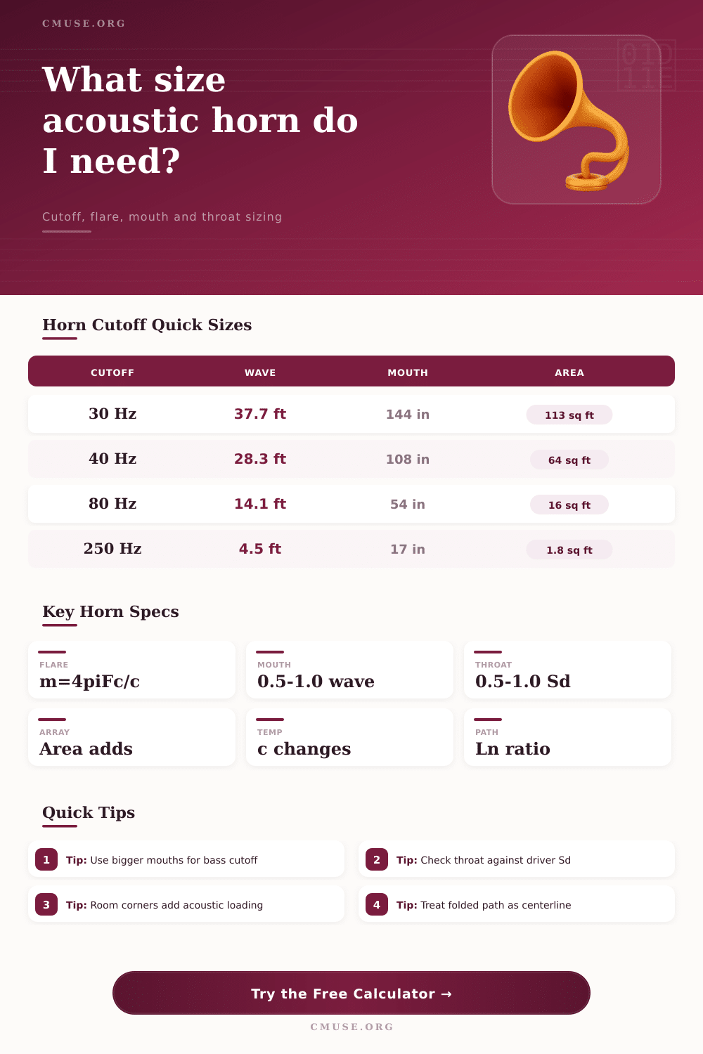
| 30 Hz | 37.7 ft / 11.49 m | 144 in / 366 cm | 113 sq ft / 10.5 m² | Large sub-bass horn or coupled array |
| 40 Hz | 28.3 ft / 8.62 m | 108 in / 274 cm | 63.6 sq ft / 5.91 m² | PA bass horn, corner-loaded bass |
| 60 Hz | 18.9 ft / 5.75 m | 72 in / 183 cm | 28.3 sq ft / 2.63 m² | Compact folded low-frequency horn |
| 80 Hz | 14.1 ft / 4.31 m | 54 in / 137 cm | 15.9 sq ft / 1.48 m² | Midbass or kick region reinforcement |
| 250 Hz | 4.5 ft / 1.38 m | 17.3 in / 43.8 cm | 1.63 sq ft / 0.15 m² | Low-mid horn loading |
Flare profile comparison for planning calculations
| Profile | Working Formula | Length Behavior | Best Fit | Design Note |
|---|---|---|---|---|
| Exponential | Sx = St e^(mx) | Reference length | Classic loudspeaker horns | Uses m = 4πFc / c directly |
| Hyperbolic | Sx = St cosh(mx/T) | Longer for low cutoff | Bass horns with strong loading | Planner uses a slower expansion factor |
| Tractrix | Radius tends to mouth limit | Slightly shorter mouth path | Midrange and vocal horns | Often chosen for smoother termination |
| Conical | Diameter grows linearly | Shortest geometric estimate | Megaphones and waveguides | Acoustic cutoff is less sharp |
Throat sizing against driver Sd
| Throat / Sd | Loading | Compression | Typical Use | Watch Point |
|---|---|---|---|---|
| 0.30 to 0.45 | Strong | High | High-output bass bins | Check excursion, heat, and distortion |
| 0.50 to 0.80 | Balanced | Moderate | General speaker horns | Common starting range |
| 0.80 to 1.10 | Gentle | Low | Low-coloration mid horns | Needs enough horn length |
| Above 1.10 | Weak | Very low | Waveguide behavior | May load less like a true horn |
Common acoustic horn project sizes
| Project | Cutoff | Throat Example | Mouth Rule | Primary Result |
|---|---|---|---|---|
| Home studio midbass | 100 Hz | 5 in / 12.7 cm | 0.75λ | About 3.4 ft / 1.0 m path |
| Practice room kick horn | 70 Hz | 7 in / 17.8 cm | 0.75λ | About 4.8 ft / 1.5 m path |
| Stage bass horn | 40 Hz | 10 in / 25.4 cm | 1.00λ | About 8.6 ft / 2.6 m path |
| Gramophone-style horn | 300 Hz | 1.5 in / 3.8 cm | 0.75λ | About 1.7 ft / 0.5 m path |
Acoustic horns can make small driver sound like they are much larger than the actual size of the driver. Acoustic horns is used in many different applications. The reason that acoustic horns are often used is that the acoustic horns helps to increase the sound output of the driver that is placed within the horn.
An acoustic horn works by providing an acoustic load for the sound waves that the driver creates. The acoustic load is strongest at frequencies above the horn’s design cutoff frequency. Below that cutoff frequency, the acoustic loading collapses.
How Acoustic Horns Work and How to Design Them
The horn’s output drops below the cutoff frequency, which means that the horn’s lowest usable note will determine the horn’s geometry. Horns with long wavelength require larger mouths to provide the horn with the behavior of a true horn rather than a waveguide. The throat of the horn must be sized appropriately relative to the size of the driver to avoid excessive compression of the sound waves at the throat.
Too small a throat will cause the horn to exhibit strong compression at the driver. Too large a throat will prevent the horn from providing the gain to the sound that the driver creates. An important factor in horn design is the effect of temperature on the horn.
The speed of sound within the horn changes with the density of the air within the horn, and the density of the air change with the temperature of the air. If a horn is calculated to work at 68 degrees Fahrenheit, but is then located in an environment with a lower ambient temperature, the horn’s sound will be altered. The horn calculator allows you to enter the desired temperature of the horn environment so as to remove the guesswork of what that cutoff frequency will be in your specific environment.
The shape of the flare of the horn will determine the way in which the sound waves expand within the horn. Different shape of acoustic horns will provide different sound characteristics. Horns with exponential flares produce equations that are mathematically easy to calculate and have a sharp cutoff frequency.
Many horn designer use exponential horns when building loudspeaker drivers. Horns with hyperbolic profiles allow the horn to reach a lower cutoff frequency then with exponential horns within the same length of horn. However, horns with hyperbolic profiles has the additional requirement of having more volume within the horn enclosure.
Tractrix and conical horns have a different set of benefits than exponential or hyperbolic horns, though they may produce less efficiency. There is no universal horn that will provide the best sound relative to the others; each horn shape places the same set of variable in a different weighting within the horn. The size of the mouth of the horn is a variable that many horn designers tend to underestimate.
Horns that are to cut at 40 hertz and below will have mouths with circumference close to one full wavelength of the horn’s cut frequency. Such a circumference is large, hence the importance of using corner or wall loading to reduce the size of the horn’s mouth. This is one of the main reasons that many bass horn are constructed to sit in the corners of a room.
The horn calculator allows you to enter a mouth circumference multiplier to help you decide how much loading you will provide to the horn. Additionally, if the horn’s mouth will not fit within the cabinet, then the horn that is designed will not function as intended; this is a requirement to consider before constructing the horn. Another important measurement for horn design is the ratio between the area of the horn’s throat and the area of the driver’s radiating surface.
Ratios between 0.5 and 08 are typically used for horns that are used in midbass and vocal application. Ratios that are lower than 0.5 will increase the horn’s output, but will also increase the heat and distortion within the horn. Ratios that are higher than 0.8 will reduce the stress placed upon the driver, but will require more path length to achieve the same acoustic gain as a horn with a throat of a more common ratio.
It is important to consider and to monitor the ratio of the throat of the horn, as this can tell you alot about the behavior that the horn will have in the real world. Folded horns are horns that use a maze-like structure within the horn to provide the horn with an increased path length for the sound waves to travel. The acoustic path length is the distance that the sound waves travel along the folded horn, rather than the straight-line distance between the throat of the horn and the mouth of the horn.
Thus, a compact cabinet can have a long acoustic path length. The horn calculator can help determine if the horn will have enough path length relative to the amount of acoustic gain that it will provide. This check will help prevent the designer from constructing a horn that does not meet the required constant for the horn’s flare.
Real rooms are rarely identical to the assumptions of horn calculations. Many objects within a room will absorb some of the high-frequency sound that the horn creates. The horn calculation formulas assume that the horn radiates into a room that has no objects that will reflect or absorb some of the horn’s sound.
Using these assumptions, the horn calculator provides a design that will work in an ideal environment. The calculated values should be treated as a starting point only; they should be measured in the actual constructed horn within the actual room. Another consideration in horn design is the number of horns that will be used.
Using two or four horns of the same dimension will increase the effective area of the horn’s mouth, but will not change the size of any of the horn cabinets. The horn calculator allows you to enter the number of horns that will be used within an array, which helps to reduce the cutoff frequency of the horns without the need to construct an enormous horn. Thus, the horn calculator allows the designer to achieve the same effect as a very large horn, but with the use of multiple horns of a smaller size.
It is recommended that you run the horn calculator twice in the creation of an acoustic horn. The first time, calculate the horn using the ideal size for the horn’s mouth. The second time, calculate the horn using the size of the mouth of the cabinet in which the horn will be constructed.
By comparing these two results, the designer can make certain that the horn will function as intended; any difference in the required path length will tell the designer how much performance is being sacrifice for the convenience of constructing a horn that can fit within the available space. This second calculation is one of the many that are a helpful part of the process of creating an acoustic horn project that will be succesful.