Coupling Capacitor Cutoff Calculator
Calculate the -3 dB high-pass corner formed by a series coupling capacitor, the driving source resistance, and the receiving stage load in guitar amps, pedals, synths, and studio line circuits.
Coupling Capacitor Results
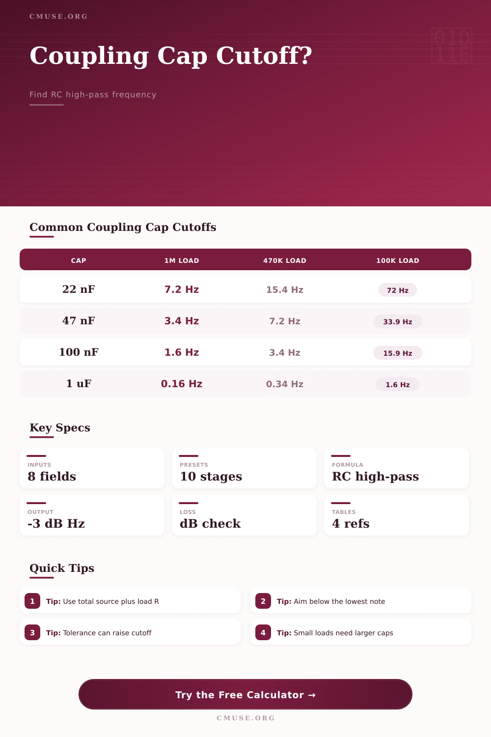
| Capacitor | 1M Load | 470k Load | 220k Load | 100k Load | 47k Load |
|---|---|---|---|---|---|
| 2.2 nF | 72.3 Hz | 153.9 Hz | 328.8 Hz | 723.4 Hz | 1539 Hz |
| 4.7 nF | 33.9 Hz | 72.0 Hz | 153.9 Hz | 338.6 Hz | 720.0 Hz |
| 10 nF | 15.9 Hz | 33.9 Hz | 72.3 Hz | 159.2 Hz | 338.6 Hz |
| 22 nF | 7.2 Hz | 15.4 Hz | 32.9 Hz | 72.3 Hz | 153.9 Hz |
| 47 nF | 3.4 Hz | 7.2 Hz | 15.4 Hz | 33.9 Hz | 72.0 Hz |
| 100 nF | 1.6 Hz | 3.4 Hz | 7.2 Hz | 15.9 Hz | 33.9 Hz |
| Signal Range | Lowest Note | Frequency | Practical Cutoff Aim | Reason |
|---|---|---|---|---|
| Standard guitar | E2 | 82.4 Hz | 8 to 20 Hz | Full fundamentals with tight sub-bass |
| Drop-tuned guitar | C2 | 65.4 Hz | 6 to 15 Hz | Keeps low chords from thinning early |
| Four-string bass | E1 | 41.2 Hz | 4 to 10 Hz | Preserves bass fundamental energy |
| Five-string bass | B0 | 30.9 Hz | 3 to 8 Hz | Avoids audible rolloff on the low B |
| Line-level full range | 20 Hz | 20.0 Hz | 2 to 5 Hz | Minimizes low-band phase shift |
| Receiving Stage | Typical Resistance | Cap Often Seen | Approx Cutoff | Design Note |
|---|---|---|---|---|
| Tube grid leak | 1M | 22 nF | 7.2 Hz | Classic guitar preamp coupling |
| Tube grid leak | 470k | 22 nF | 15.4 Hz | Common after mixing or attenuation |
| Master volume input | 250k | 22 nF | 28.9 Hz | Can trim low end before overdrive |
| Pedal or amp input | 1M | 100 nF | 1.6 Hz | Nearly flat for instrument bandwidth |
| Studio line input | 47k | 4.7 uF | 0.72 Hz | Electrolytic values are common here |
| Low-Z processor input | 10k | 10 uF | 1.6 Hz | Large cap needed because load is small |
| Cap Type | Common Range | Typical Tolerance | Audio Coupling Use | Cutoff Impact |
|---|---|---|---|---|
| Film polyester | 1 nF to 1 uF | 5% to 10% | Tube and pedal signal coupling | Stable marked value |
| Film polypropylene | 1 nF to 470 nF | 2% to 10% | Precision line or hi-fi coupling | Very predictable cutoff |
| Ceramic C0G | 10 pF to 10 nF | 1% to 5% | Small bright caps and filters | Good for small high-pass caps |
| Electrolytic | 1 uF to 100 uF | 20% typical | Low-impedance line and op-amp stages | Low-side tolerance raises fc |
| Bipolar electrolytic | 1 uF to 47 uF | 10% to 20% | Speaker-level or uncertain polarity paths | Check worst-case capacitance |
You spend hours tinkering with pedals and adjusting a tube’s bias looking for that magic sound in the low end but never quite getting there. Often times, the problem is right there on the schematic. It’s called the coupling capacitor.
Coupling capacitors blocks DC voltage but let an audio signal (AC) pass from one amplifier stage to another. At the same time they function as a high-pass filter. If you don’t select the correct value, bass frequencies is rolled off prior to reaching the next amplifier stage.
How to Choose the Right Coupling Capacitor
The mathematics of this relationship are simple enough that any builder can confirm for themself. But many builders do not consider what the true resistance is being seen by capacitor and therefore still get it wrong. So how does it work? It’s all based off one of the most basic relationships in an RC high-pass filter. Take the input impedance of following stage plus the resistance of the drive coming from the preceding stage. This adds up to total resistance in the circuit. When combined with the capacitor value, this total resistance determine the cutoff frequency where the signal drops by three decibels.
Most designers should of aim for a cut-off frequency that is far below the lowest note you plan to play. Your bass guitar has a low-E string of 82 hertz but your -3 dB point is also at 82 hertz. That means you’ve already lost a quarter of your signal at the very fundamental frequency. So bass guitar players require significantly higher values of capacitor than their electric guitar counterparts because they’re battling nature to maintain those lower frequencys intact.
You’ll see the calculator on top of this page asking for both the load and source resistances, and that’s important: higher impedances such as those found at the output of a tube amp can be many megohms. That lets even small caps such as 22 nanofarads through without trouble at low end. However, plug the same signal into an effect pedal whose input impedance might be just 10 kilohms and suddenly the cutoff frequency leap up into the hearing range. Because the heavier load pushes the corner of the high-pass filter upward, it moves into the hearing range and makes your sound thin. To make up for the large load, you need to change out to a much bigger cap. It isn’t simply a matter of the part itself; it’s a matter of its interaction with what follows it.
Electrolytic caps also figure into this quietly due to their use in low impedance circuits where capacitance is critical, but tolerance isn’t necessarily always so. Electrolytic caps has high capacitance in compact packages but frequently with broad tolerances of 20 percent or wider. So if you design your circuit around a precise cut-off frequency but purchase a cap that’s just below its tolerance limit for whatever reason, your effective cap becomes reduced and your carefully designed flat response suddenly rolls off at bass end. This is a subtle little detail that can spoil an otherwise sound build, so it pays to design in a bit of headroom.
In most cases, real world audio engineering are about managing trade-offs and understanding phase shifts at the low end, and how those changes affect the overall mix while working within the limits of available equipment. You might have calculated a low enough cutoff point. However, the resulting phase change caused by filtering has slowed down the transient response of your instruments, causing sluggish bass guitar or less punchy drums. Rather than fixed rules, the included reference tables is a good place to start. You’ll want to take into account what your actual equipment puts out to the circuit.
So, what should you choose? In truth, picking the right coupling capacitor isn’t so much about remembering formulas as it is understanding the signal path. Each stage of your signal chain create an impedance profile that will affect the following stage. Considering component tolerance plus the resistance of both source and the load, you can assure that every step from input to output is true to your desired tone.
Instead of relying on guesses, you want your lows to rumble without being muddied by interference. Precision, not guesswork. If you make the effort to check these numbers, you’ll cease battling equipment limitations and begin confidently shaping your sound. Getting that high-pass corner exactly where you want it can make all the difference between a thin, nasal tone and a full, rich response.