Clip Point Calculator
Estimate where an audio path clips by converting analog level, dBFS calibration, voltage swing, crest factor, and gain changes into practical headroom.
Load a common studio, stage, instrument, or converter scenario. Each preset sets analog clip level, converter calibration, present peak level, crest factor, margin, and load.
Clip Point Breakdown
dBu To Voltage
Vrms = 0.775 x 10^(dBu / 20)Use this for professional analog line levels and balanced output clip specifications.
dBV To dBu
dBu = dBV + 2.21Consumer -10 dBV is about -7.79 dBu, so it clips differently against pro inputs.
dBFS To Analog
Peak dBu = Cal dBu + dBFSIf +24 dBu equals 0 dBFS, a -12 dBFS true peak maps to +12 dBu.
Safe RMS Ceiling
RMS dBu = Clip - Safety - CrestHigher crest factor needs more peak clearance even when average level looks moderate.
| Audio Path | Typical Clip Point | Nominal Reference | Nominal Headroom |
|---|---|---|---|
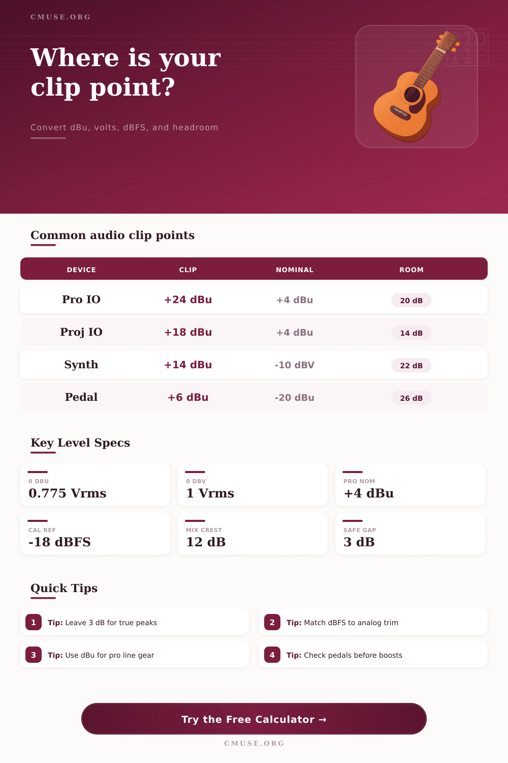
| High-headroom pro converter output | +24 dBu | +4 dBu | 20 dB above nominal |
| Compact project studio interface | +18 dBu | +4 dBu | 14 dB above nominal |
| Broadcast or installed processor chain | +22 dBu | +4 dBu | 18 dB above nominal |
| Synthesizer or sampler line output | +14 dBu | -10 dBV, about -7.8 dBu | about 21.8 dB above nominal |
| Instrument pedal or hot DI stage | +6 dBu | -20 dBu to -10 dBu | 16 to 26 dB by setup |
| Signal Type | Working True Peak | Typical Crest Factor | Clip Point Note |
|---|---|---|---|
| Full mix bus before limiter | -12 to -6 dBFS | 10 to 14 dB | Keep room for plug-in and converter trims. |
| Vocal channel with compression | -10 to -6 dBFS | 8 to 12 dB | Watch clip lights after EQ boosts. |
| Drum bus or percussion stem | -14 to -8 dBFS | 12 to 18 dB | Fast transients need wider safety margin. |
| Synth pad or sustained keyboard | -10 to -4 dBFS | 5 to 10 dB | Average level can sit closer to the clip point. |
| Mastering converter send | -6 to -3 dBFS | 6 to 10 dB | Verify true-peak metering before final capture. |
| Level | Vrms | Sine Peak | Peak To Peak |
|---|---|---|---|
| +4 dBu | 1.23 V | 1.74 Vpk | 3.47 Vpp |
| +14 dBu | 3.88 V | 5.49 Vpk | 10.98 Vpp |
| +18 dBu | 6.16 V | 8.71 Vpk | 17.42 Vpp |
| +24 dBu | 12.28 V | 17.36 Vpk | 34.72 Vpp |
| +28 dBu | 19.46 V | 27.52 Vpk | 55.04 Vpp |
| Load | +14 dBu Sine | +18 dBu Sine | +24 dBu Sine |
|---|---|---|---|
| 600 ohms legacy input | 25.1 mW | 63.2 mW | 251.4 mW |
| 2 kohms instrument input | 7.5 mW | 19.0 mW | 75.4 mW |
| 10 kohms line input | 1.5 mW | 3.8 mW | 15.1 mW |
| 100 kohms high-Z input | 0.15 mW | 0.38 mW | 1.51 mW |
This might be confusing as you hear something sounding right on screen and wrong when its printed. More often than not, this isn’t because of poor taste, but because person doesn’t understand what actual problem is.
Analog equipment has physical limitations whereas digital ones has numbers in some abstract form. When your interface hits full voltage it’s signified by a red light. If you know what that means, then the waveform does not flatten out. DBFS is considered by many user to be volume standard. After all, it is an absolute value in digital form, where anything below zero result in hard clipping.
Understanding Volume Levels
But consider there is also an analog input stage on audio interface that converts soundwaves to voltage. That stage also have a maximum limit. For example if your input stage clips at +24 dBu and you feed it +26 dBu it will distort well before the signal reach digital data.
There are tools such as calculators that do math for you after you input what equipment you have so you don’t need to guess about any conversions. This links world of digital numbers with real-world of voltage, removing the abstraction.
First you need to determine how high you want your device to go. Some professional interfaces will clip at +24 dBu and some smaller project boards might max out at +18 dBu. That’s your absolute stop.
Now think about your setup. Are your converters set up so that 0 dBFS = +24 dBu? In other words, if you have a signal in your DAW reaching -3 dBFS that means it’s dangerously near analog ceiling. To avoid that, headroom is needed. You can manage that risk by setting a safety margin in the device. Setting three decibels under the clip point leave enough space for intersample peaks. These are small spikes between digital sample that can be higher than true peak shown on the meters.
Incorrect assumptions is made about headroom due to crest factor. For example, a drum bus might appear loud yet have gaps of silence, or a synth pad could be quiet on average yet have sharp transients. Crest factor is distance between the highest peak and the average level. Failure to account for this results in thinking that the preamp hasn’t clipped because the RMS meter is low while the snare hit were actualy clipped. With the tool, you can then figure out a safe average level by taking into account your remaining headroom minus the crest factor. This comes into play when attempting to improve signal-to-noise ratio while avoiding distortion.
The other source of voltage confusion come from the fact that there is two primary standards used by the industry for voltage levels. On professional side, the nominal level is +4 dBu (about 1.23 volts RMS). For consumer/semi-pro equipment, the standard tends toward -10 dBV, a lower signal level. Not understanding the voltage swing of your equipment will lead you to connect something with higher output, like a synth, into a sensitive pedal input, resulting in colored sound and possibly even unwanted clipping. Converting volts to dBu helps make this clearer. A dBV level of 0 represents one volt RMS, while approximately +2.2 dBu represent a voltage of one volt RMS.
When multiple effects is stacked together, or EQ settings are boosted, those additional decibels adds up rapidly.
Keep it Clean, Not Quiet Instead of trying to make a signal quiet, we’re going to try to make it clean. It is hot enough to obscure preamp noise, but low enough to never hit the ceiling on a peak. You should of kept it clean.
The tool has preset buttons for typical chain setups like mastering chains or live consoles. These buttons displays how much gain remains after taking into account tolerance errors and safety margins.
It’s not about being afraid of the red light. It’s about knowing exactly where the line is drawn in the signal chain, this lets you push your levels right up against it without crossing over. You would of felt more comfortabley if you knew the math.