Allpass Delay Alignment Calculator
Estimate the delay offset between two audio paths, convert acoustic distance into time, and solve a first-order all-pass coefficient for frequency-focused alignment.
Load a realistic studio, live sound, or instrument-miking scenario. Each preset sets the measured offset, crossover or dominant frequency, sample rate, path distance, and all-pass stage count.
The coefficient solve uses a first-order digital all-pass form H(z) = (a + z^-1) / (1 + a z^-1). Group delay at the selected angular frequency is matched per stage when a stable coefficient is possible.
Formula Breakdown
| Source Pair | Useful Band | Typical Offset | Alignment Focus | All-Pass Caution |
|---|---|---|---|---|
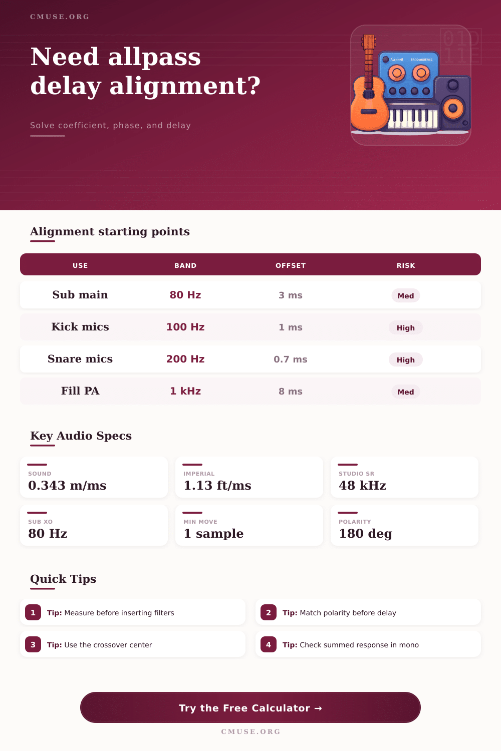
| Subwoofer and main speakers | 60 to 120 Hz crossover | 2 to 8 ms | Summed crossover amplitude and impulse arrival | Use narrow evaluation around crossover, not full-band tone matching. |
| Kick drum inside and outside microphones | 60 to 150 Hz body plus click band | 0.5 to 2 ms | Low-end punch and polarity-compatible transient shape | A pure delay may be cleaner when both mics share the same source. |
| Snare top and bottom microphones | 150 to 250 Hz shell plus 2 to 6 kHz snap | 0.2 to 1.2 ms | Polarity, shell tone, and top/bottom comb filtering | Flip polarity first; all-pass cannot replace wrong polarity. |
| Guitar amp microphone and DI reamp path | 90 Hz to 3 kHz | 0.3 to 4 ms | Pick attack, cabinet resonance, and DI thickness | Multiple frequency bands may need listening checks after the solve. |
| Piano spot pair and room pair | 120 Hz to 2 kHz | 1 to 12 ms | Image stability without collapsing room depth | Partial correction often sounds more natural than full correction. |
| PA fill speaker and main array | 500 Hz to 2 kHz speech clarity | 5 to 35 ms | Arrival priority and intelligibility in the overlap zone | Use real acoustic measurement at listener position. |
| Reference | At 44.1 kHz | At 48 kHz | At 96 kHz | Acoustic Distance |
|---|---|---|---|---|
| 1 sample | 0.0227 ms | 0.0208 ms | 0.0104 ms | 0.28 in / 7.1 mm at 68°F |
| 0.5 ms | 22.1 samples | 24 samples | 48 samples | 0.56 ft / 0.17 m |
| 1 ms | 44.1 samples | 48 samples | 96 samples | 1.13 ft / 0.34 m |
| 5 ms | 220.5 samples | 240 samples | 480 samples | 5.63 ft / 1.72 m |
| 10 ms | 441 samples | 480 samples | 960 samples | 11.26 ft / 3.43 m |
| Per-Stage Group Delay | Coefficient Behavior | Best Use | Warning Sign |
|---|---|---|---|
| Below 0.25 sample | Coefficient often approaches a small phase trim | Fine transient nudging at higher frequencies | May be too subtle to solve at very low frequency. |
| 0.25 to 2 samples | Usually stable and easy to automate | Mic and crossover phase cleanup | Still verify with polarity and magnitude response. |
| 2 to 12 samples | Can require negative coefficients near low bands | Subwoofer or fill alignment around one band | Cascade stages if one coefficient becomes extreme. |
| Above 12 samples | Better handled by pure delay plus all-pass trim | PA fills, distant room mics, large acoustic offsets | Full-band timing may smear if all-pass does all the work. |
| Project | Frequency Target | Starting Delay | Preferred Tool | Check Result |
|---|---|---|---|---|
| Small studio sub integration | 80 Hz | 2 to 5 ms | Delay for distance, all-pass for crossover phase | Smooth summed response through crossover. |
| Drum close and overhead blend | 150 to 400 Hz | 1 to 4 ms | Partial delay or polarity-aware all-pass | Snare stays centered and low mids do not hollow out. |
| Guitar DI with cabinet microphone | 700 Hz to 2 kHz | 0.5 to 3 ms | Small delay first, all-pass if tone shifts by band | Pick transient gets thicker without nasal combing. |
| Side fill to main PA | 800 Hz to 1.6 kHz | 8 to 25 ms | Pure delay plus small phase trim | Main image remains dominant in overlap area. |
| Spot mic and room mic | 100 to 600 Hz | 5 to 20 ms | Partial correction only | Room depth remains musical while lows align better. |
Your kick drum sounds like a hammer in isolation, but gets lost in mush when you bring up the overheads. You check levels…nothing seems amiss. You reach for EQ or maybe the panner. But probably it’s not about tonal balance. Time. Comb filtering caused by soundwaves arriving at mics at varying phases, dependent off distance, cuts out the low end before our ears catch onto the timing problem.
This can be solved with an allpass delay alignment calculator, separating phase shifts that change with frequency from pure time offset. They’re not interchangeable, and you need to know which one do what. Where things get tricky is that “regular” delay lines affect all frequencies the same amount, whereas all-pass filters merely shift phase and don’t alter magnitude response. That’s important when aligning an amp microphone to a DI feed, or matching up a subwoofer to the other main speaker. Delaying the second by just the measured difference may correct the timing of transients, but it can also create a hole in the phase response at the crossover frequency.
How to Fix Timing Problems in Your Mix
With that tool we’ve created above, you input the electrical offset or the acoustic path difference, then convert it to millisecond delay and number of delay samples. Then it spits out a reliable filter coefficient for you to use and removes any guesswork on how much delay to apply to which stage of the filter.
To begin: Measure how far apart your main and backup pickup spots are from original source. Each additional mic placement or each extra foot of cable means approximately one millisecond more time for audio to travel. This can be significant and create severe cancellation in the low end (bass) range. The device requests that specific amount of delay, as well as the air temperature, since temperature affects speed of sound. Warmer air will carry the sound faster, so there’s a bit of a change in delay.
It also requires knowing what frequency you’re concerned about, like a 2 kilometer snare snap, or an 80-hertz speaker crossover point. That way the calculator knows just how hard to work on that particular area instead of all over the place. It produces an all-pass filter that has a first-order output, using the coefficient you need to add the desired group delay at the target frequency.
The coefficient needs to be in the range from negative one to positive one; it has to be stable. When it reaches its limits and cannot handle the desired delay by itself, it will become unstable. In this case, you can use multiple stages (cascade) or abandon the all-pass filter and use a straight delay line. The calculator lets you know if the solution is getting close to the stability boundary.
It also shows you how much timing error remains once you apply whatever delay you’ve selected as a correction. In some cases you may not wish to align completely. For instance, leaving 20% of the offset intact keeps the natural sense of room depth. This adds a three-dimensional quality to recordings, making them sound more real rather than flat and fake.
Another silent killer is polarity. Delay or phase rotation won’t fix a flipped microphone or make the low end sit right. The ability to mark this polarity relationship on the tool means it’ll flag a possible problem in the results. Bottomline: Always check the polarity by summing to mono and listening for loss of bass prior to believing any coefficient.
When polarity’s sorted, then apply most of the required time offset via delay line, reserving the all-pass filter for phase fine tuning around the critical frequency. A hybrid approach give you the smooth sound of phase management along with the punch of transient alignment.
Similar issues arise with live sound, but over greater distances. Aligning a stage fill to the main array requires managing delays in the range of tens of milliseconds. Again, the arrival time is handled automatically by simple delay; it makes sure the direct sound reaches the ears first, followed by the delayed/reflected sound. An all-pass filter would of been too delicate for such a great gap. Only consider this if your timing mismatch is slight enough to cause some comb filtering within the vocal midrange. This should be a mismatch that cannot be resolved by moving the speakers physically.
The distance and sample rate conversion factors found in the reference tables on the page can serve as a handy reference when you’re troubleshooting without software/power. It isn’t about mathematically correct alignment. It’s about musical coherence. Sometimes perfect alignment can feel lifeless. This is especially true in ensemble recordings or those using room mics, which add some time variation to create space and width.
Using the calculator will lead you to the sweet spot, where the naturaly ambience is preserved but destructive interference is corrected. You dial back and forth on the percent of correction till the resulting sum has focus and fullness while still maintaining the air surrounding the instruments. It is a balancing act between perception and physics.
Afterward, use these coefficients and delay times as presets for later sessions with comparable acoustics. Consistent alignment methods minimize trial and error in the mixdown. You will spend more time crafting tone and less time chasing elusive low end. Your confidence in interpreting the numbers into audio grows with experience.
Believe your ears more than the display. However, the calculator does the grunt work of turning frequency and distance into adjustable filter values. Begin with the measurements. Apply them lightly and then wait to hear the bass come back. That’s how you take a muddy mix and convert it into a solid foundation.