Ceiling Bounce Frequency Calculator
Estimate the ceiling-reflected path, path difference, comb-filter nulls, mirror point, reflection angle, and cloud absorption for stereo rooms, desks, booths, and listening spaces.
Calculation breakdown
Bare drywall
0.05
midband absorption coefficient
2 in cloud
0.70
useful above lower mids
4 in cloud
0.88
strong ceiling bounce control
4 in plus gap
0.96
best lower-null coverage
Comb-filter nulls
| Null | Frequency | Cause | Severity |
|---|
Comb-filter peaks
| Peak | Frequency | Path relation | Note |
|---|
Ceiling reflection grid around mirror point
| Grid point | Offset along path | Offset across path | First null | Cloud cover |
|---|
Cloud material comparison
| Ceiling treatment | Alpha | Reduction | Best use |
|---|
Room setup reference
| Setup | Typical distance | Mirror area | Cloud target |
|---|---|---|---|
| Desk mix | 3.5 to 5 ft | front half of ceiling | 2 x 4 ft minimum |
| Nearfield studio | 4 to 6 ft | between desk and chair | 4 x 4 ft or larger |
| Console room | 5 to 8 ft | above console bridge | 4 x 6 ft plus gap |
| Home theater | 7 to 12 ft | between screen and row | wide cloud or absorptive tile |
Most mixers concentrate on wall treatment and speaker placement, but they rarely thinks about the ceiling above them. A ceiling is an enormous acoustic mirror. Your ears recieve reflections off the ceiling just moments following the direct sound. With sufficient energy it will smears the transients while muddying the low mid frequencies. That’s when we get that comb filter creating both peaks and nulls in the tonal balance. The actual signal hasn’t changed but how it sounds has.
How do you know? Well this calculator here make those calculations for you. It takes your room size and turns it into estimates at certain frequencies. This makes it easier to target the issue different than having to guess where to apply foam.
Why Your Ceiling Matters for Sound
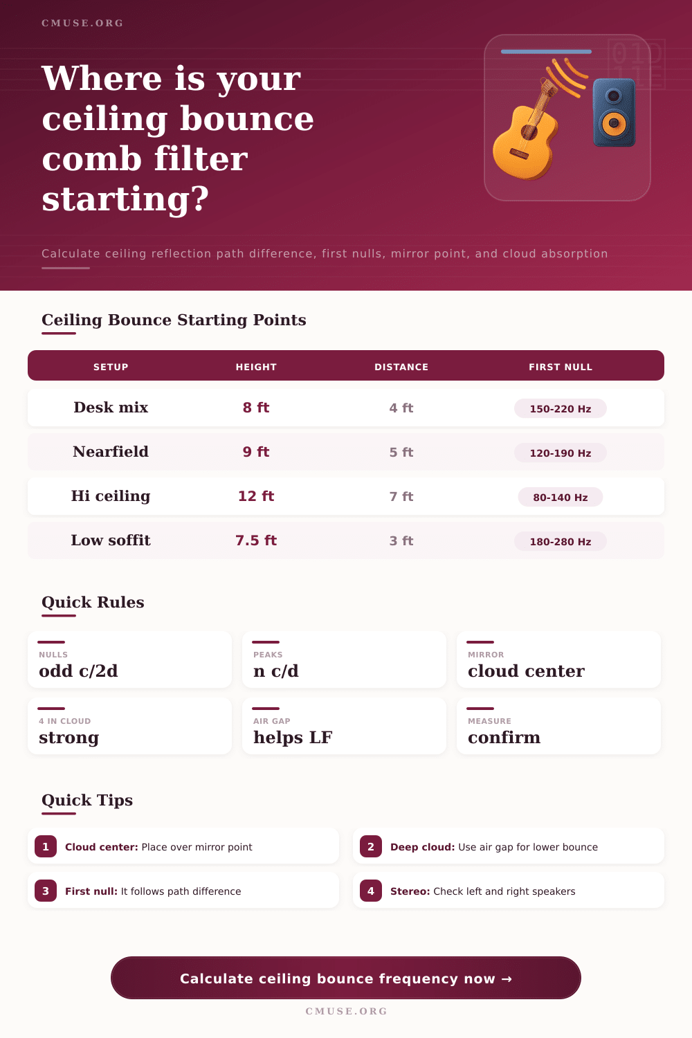
The starting point for that understanding is the mirror point, the location on the ceiling where reflected sound returns to your ears. It’s a function of separation between speakers, their height above the floor and the height at which you’re listening. When the mirror point is not directly in front of an absorptive cloud, it’s being treated in the wrong place. The tool recognize vertical offsets (because tweeters aren’t typically at ear-level) and a few inches can move the mirror point either closer to speaker or listener. That changes the path length, and therefore changes the frequency of the initial cancellation null.
Phase problems is clear at the first null. This is the lowest frequency that gets canceled out by the phase relationship between the direct sound and its delayed reflection. For an ordinary room with 8-foot ceilings, it commonly occurs in the vocal presence range making voices sound nasal or thin. Calculating the frequency use the speed of sound which has some variation due to air temperature. Accuracy helps avoid wasting time in getting the sound right for a critical listening environment.
Most of the time the fix is a cloud on the ceiling, only not every cloud are created equal. Thin sheets of felt can lessen some of the harshness in higher frequency sounds while leaving nulls below the midrange untouched. To address those low frequencies require depth and mass. And when you look at reference information, a 4 inch broadband panel with an air gap perform much better then thin foam or bare drywall. The air gap matters as it allows the material to absorb longer wavelengths by vibrating into them. If no air gap exists then they will bounce off the surface of the fabric. That’s what causes the trap that then absorbs energy rather than reflecting back downward where it could interfere with direct sound.
How much sound reflects also depend on how speakers direct their sound. If your monitors has narrow vertical dispersion, they will throw less energy upward, which reduces intensity of the bounce. Speakers with wider dispersion light up the ceiling and consequently produce a stronger comb filter effect. Selecting from the narrow, medium or wide directivity profiles cause the tool to adjust the estimates accordingly. This helps you understand that some gear just needs more love than other gear.
When fixing a room you have to consider not only frequency response but also the time delay. Learning about the mirror point and how cancellation is produced by path difference allow us to go beyond trial and error placement and intervene purposefully. Adding a well-placed cloud positioned over the calculated point will clean up the reflections above you while keeping the direct sound coming in from below clear. It would of been more effective than a whole wall of bass traps.