Zobel Network Calculator
Calculate a series RC Zobel network for a loudspeaker voice coil, including resistor value, capacitor value, cutoff frequency, impedance flattening, power rating, and parallel RC response.
Calculation Breakdown
| Frequency | Raw speaker impedance | Zobel branch | Parallel total | Flattening | Resistor heat |
|---|---|---|---|---|---|
| Calculate to fill the sweep. | |||||
| Network seen by crossover | Impedance at Fc | 1st order cap | 1st order coil | 2nd order cap | 2nd order coil |
|---|---|---|---|---|---|
| Calculate to compare raw and flattened loads. | |||||
| Part | Exact value | Nearest common | Low tolerance edge | High tolerance edge | Practical note |
|---|---|---|---|---|---|
| Calculate to fill part suggestions. | |||||
| Test frequency | Zobel current | Resistor watts | Recommended part | Cap RMS volts | Reading |
|---|---|---|---|---|---|
| Calculate to estimate branch stress. | |||||
| Design choice | What changes | When to use | Caution |
|---|---|---|---|
| Rz equals Re | Strongest theoretical voice coil compensation | Measured passive crossover design | Can draw more high-frequency current |
| Rz equals 1.1 to 1.3 x Re | Slightly gentler flattening and less heat | Most speaker crossover starting points | Response may still rise a little |
| Larger capacitor | Compensation starts lower in frequency | When crossover region still sees impedance rise | More branch current near upper midrange |
| Smaller capacitor | Compensation starts higher in frequency | When only top octave flattening is needed | Less help at crossover frequency |
| Higher resistor wattage | Runs cooler and survives peaks better | High power woofers and PA systems | Use non-inductive types where possible |
It all begins with a dream: My speakers will sound perfect. And for most DIY speaker projects, it ends there…in a crossover that sounds like it was designed by a blindfolded accountant. The cause is seldom poor components. More often it’s an impedance curve that rises more higher than anticipated in the treble. Why? Each voice coil has inductance, so as frequency rise, that inductance adds impedance or resistance to the current flow. That results in a speaker’s apparent impedance shooting upward, which appears to a crossover network as if you are chasing a moving target. Filter frequencies shifts, phase alignment drifts, and then there’s the Zobel network, whose purpose is to pin that impedance down so that your crossover sees a steady load rather than a rollercoaster.
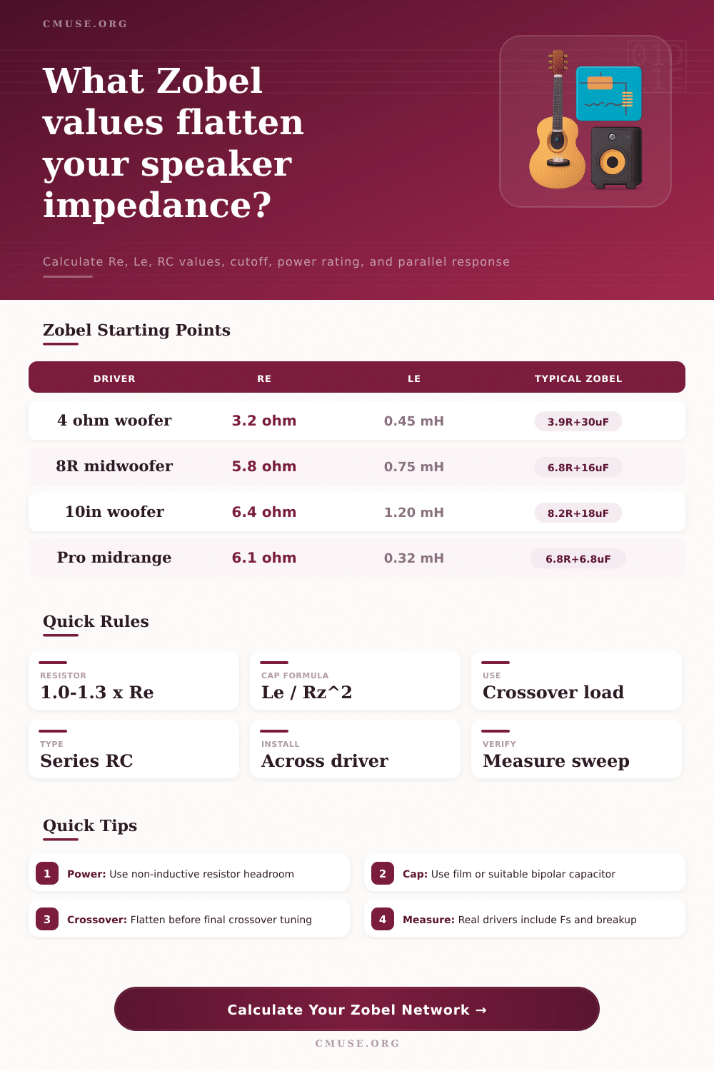
It’s surprisingly simple math. Here are the components: a resistor equal to the DC resistance of the voice coil. Next, a capacitor that cancels inductive reactance. Connect both in series and wire them across the speaker terminals. They combine to present a flat resistive load to amplifier at frequencies above some frequency.
How to Build a Zobel Network for Speakers
The calculator above will do the math for you when you enter your measured Le and Re values. It spares you having to guess which standard component values approximates the ideal. All you have to do is make good measurements. Many builders just assume from the manufacturer’s data sheet that Le is close to 1 kHz for the inductance. And though it appears to be fiddly, it isn’t nearly so bad. To measure inductance, use an LCR meter if you have one, or connect a known resistor in series (see the series resistor method). Since most drivers are generic or vintage, measure yours.
Get it wrong and using the wrong inductance value will throw off the capacitor calculation. Under-correct and the tail hangs up, cancelling the benefit of correction altogether. Over-correct and the impedance dips too low at higher frequencies. It is a little thing. Yes, but it is important for stability.
As for the resistor, pay equal attention to this part of the equation. According to textbooks, make sure the resistance is matched to the DC resistance exactly. Reality-wise, a little extra resistance makes the Zobel cooler and doesn’t hurt too much. You’ll often see a ratio of 1.15 times the Re. This keeps impedance fairly flat for crossover purposes and also keeps the Zobel cooler. Remember: that resistor exists in parallel with driver.
At loud volumes, it sees voltage. Drive an 8 ohm woofer hard and an underrated resistor will glow red. Use a metal film or wirewound one marked with enough headroom. If you intend on kicking it out, don’t go cheap with carbon composition ones. These types will drift with time and simply can’t stand the thermal loading required from long periods of high levels.
For minimal losses, opt for a reliable cap that won’t fail at high frequencies. Non-polyester film type is best. Electrolytics has no place in signal paths when precision matters, reserve these for your power supply.
Flatten the impedance first when designing crossovers. A flat 8 ohm load is much easier to tune a filter for than one that rises to 15 ohms at tweeter range. Measure the parallel impedance after installing the Zobel network. You are looking for a straight line. If it still wiggles then doublecheck the driver parameters. No simple RC pair will be able to fix all the flaws of a real driver, there are both mechanical resonances and breakup modes. The Zobel takes care of the inductive rise. Measurement gear and ears is needed for final tuning.
A sweep signal can confirm whether your impedance remains flat across your crossover region. Keeping it flat means your passive filters will act as they do in circuit simulators. Not so? Back off on your component values or realize that some drivers gets all crazy up high and you’ll have to live with it. Part of building speakers is part science and part stubbornness.
First flatten the load, then fret over sound. Everything else falls into place.