Tractrix Horn Calculator
Calculate a tractrix horn from cutoff frequency, throat diameter, mouth radius, axial length, area expansion, profile coordinates and compression driver fit.
Calculation breakdown
| Station | Axial distance from throat | Radius | Diameter | Area | Expansion from throat |
|---|---|---|---|---|---|
| Calculate to fill the tractrix profile coordinates. | |||||
| Check | Your value | Preferred range | Interpretation |
|---|---|---|---|
| Calculate to compare the driver and horn throat. | |||
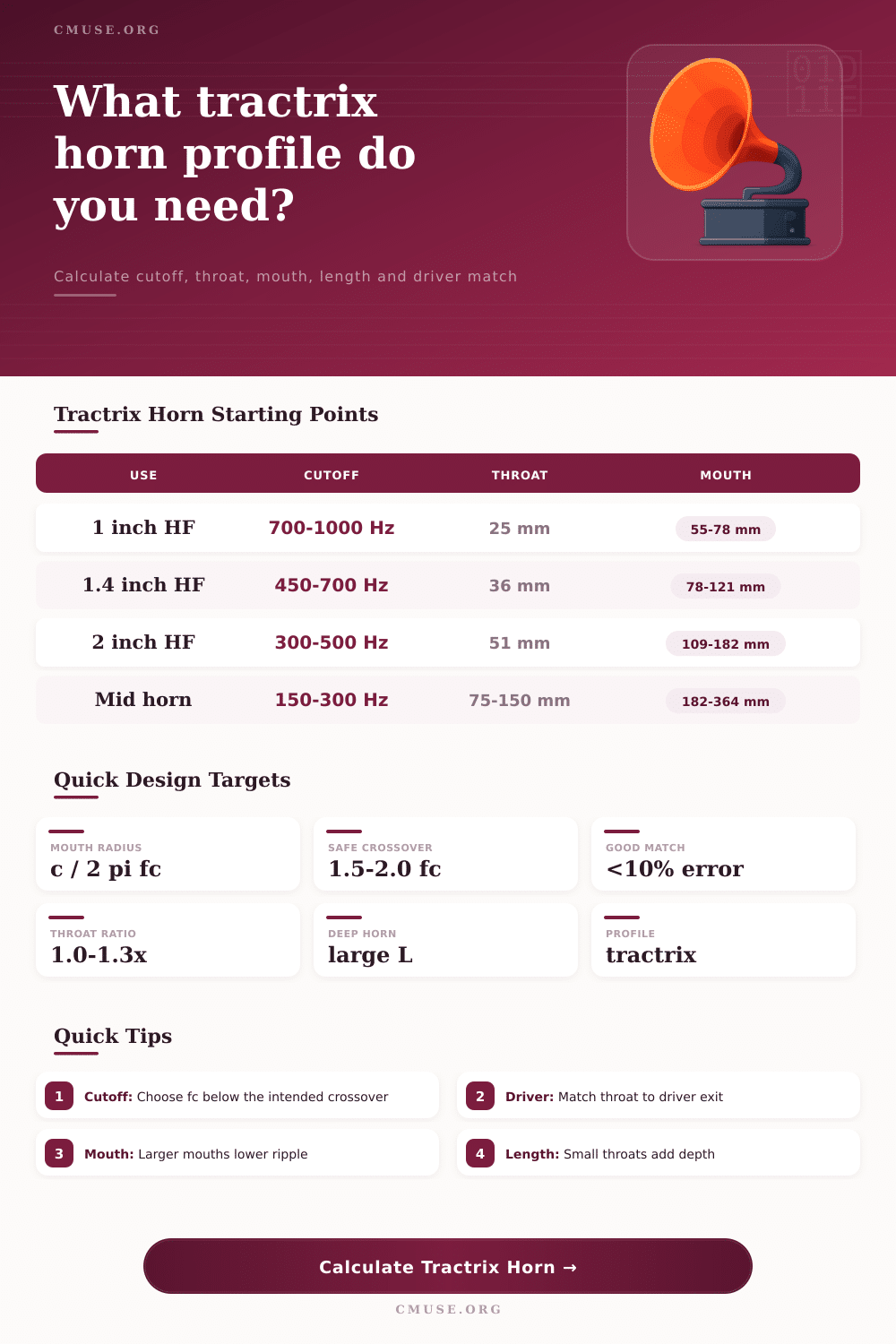
| Horn role | Cutoff target | Typical crossover | Common throat | Design note |
|---|---|---|---|---|
| Small tweeter horn | 1000 to 1600 Hz | 1800 to 3500 Hz | 19 to 25 mm | Short profile, narrow mouth, good for supertweeter or compact waveguide work. |
| 1 inch compression driver | 650 to 1000 Hz | 1200 to 2000 Hz | 25.4 mm | Useful two-way top end if the driver can handle the acoustic load. |
| 1.4 inch compression driver | 400 to 700 Hz | 700 to 1200 Hz | 35.6 mm | Common hi-fi and studio horn range with moderate physical depth. |
| 2 inch compression driver | 250 to 500 Hz | 500 to 900 Hz | 50.8 mm | Large format driver range where mouth size and room placement matter. |
| Low-mid horn | 120 to 250 Hz | 250 to 500 Hz | 75 to 150 mm | Physical size grows quickly; folding or sectional construction may be needed. |
| Preset | Cutoff | Throat | Driver exit | Why it is useful |
|---|---|---|---|---|
| 1 in 800 Hz | 800 Hz | 25.4 mm | 25.4 mm | Compact high-frequency tractrix starting point. |
| 1 in 650 Hz | 650 Hz | 25.4 mm | 25.4 mm | Deeper one-inch horn for lower crossover experiments. |
| 1.4 in 500 Hz | 500 Hz | 35.6 mm | 35.6 mm | Balanced large-format home and monitor horn. |
| 1.4 in 400 Hz | 400 Hz | 35.6 mm | 35.6 mm | Larger mouth for lower two-way or three-way handoff. |
| 2 in 300 Hz | 300 Hz | 50.8 mm | 50.8 mm | Large format compression driver horn with strong loading. |
| 200 Hz Mid Horn | 200 Hz | 100 mm | 90 mm | Direct radiator or cone-driver throat planning example. |
| Quantity | Calculator formula | Meaning | Practical warning |
|---|---|---|---|
| Cutoff radius | a = c / (2 pi fc) | The mouth radius used by the ideal tractrix curve. | Small fc values make the horn grow very quickly. |
| Axial coordinate | x = a ln((a + sqrt(a^2 - r^2)) / r) - sqrt(a^2 - r^2) | Distance from the mouth plane back toward a given radius. | The curve tends toward infinite length as the throat radius approaches zero. |
| Area expansion | Sm / St = (rm / rt)^2 | How much the horn area opens from throat to mouth. | Very high expansion can be hard to package and brace. |
| Crossover margin | fx / fc | How far the electrical/acoustic crossover sits above cutoff. | Values below 1.5 usually need careful driver testing. |
A horn loudspeaker is essentially a piece of woodworking and acoustic engineering. A design goal are to achieve some combination of control and efficiency while attempting to harness energy from a compression driver into a shaped tube. One popular profile is tractrix due to its ability to expand smoothly with minimal reflection of waves, but doing the math in your head get tedious.
Define your parameters, enter them into horn calculator above, and let the tool do the work, it’ll take the target (e.g., cutoff frequency) and spit out concrete values for axial length, throat, and mouth. Your starting place will be based off what crossover frequency you want to use with your driver. Knowing this tell us how low your horn should of be able to go (acoustic cutoff). You’ll want to make sure your horn has an acoustic cutoff well above whatever your crossover frequency happens to be so that you get a nice sounding response.
How to Use the Horn Calculator
For example: if your planned crossover point is at 800 Hz, then ideally you’d have your horn designed for a cutoff that is at least 1.5x below that frequency. Otherwise the horn might start behaving like a resonating tube down low, resulting in peaks on your frequency response. This ratio are also checked by the tool, and it alerts you to any designs where the crossover is more closer than the geometric limit.
The other important input is the throat diameter which go straight back into the compression driver. Different drivers has different sized exits for most. Matching that throat to the horn will give good efficiency of energy transfer. If not it lead to distorting the sound and causing turbulence. This will ruin what you are trying to get, a clean sound. The temptation may be to reduce the size of the throat to increase output, but all this do is increase the stress on the diaphragm and add unwanted harmonics. What the calculator then does is compare the throat size you select to driver exit and gives you a clear match rating. So, before you cut any MDF or wood you can see if there is a discontinuity.
The size of a horn’s mouth also influence how it loads the driver at low frequencies and how much of the horn interact with the room. A larger mouth can provide lower cutoff, but also means you need more room and careful attention to baffle design to prevent diffraction issues. You can change that with the tool depending on whether the horn is mounted as a free standing unit or mounted on a wall or corner. Each of these have an effect on how loaded it actualy is, which is why each boundary condition is included in the math. If you’re really trying to squeeze a horn into some kind of cabinet, you’ll probably want to bump up the mouth factor to make up for your lack of space. You pay a little price in ripple for it.
The other element that will come as a surprise with these tractrix designs is axial length. Because the curve approach an asymptote near the throat, a horn can be quite surprisingly long for modest expansions. That depth affects both how it fits into a cabinet and how the speaker fit into a room. And the point is that you’ll have exact points to plot out thanks to the profile coordinates generated by the tool so that the curve are mathematically precise from the throat to the mouth. You don’t need to derive the logarithmic functions yourself, just rely on the grid it gives you.
The material selection also factor into interior size. Because heavier materials with thicker walls shrink the horn, they also reduce the interior air pathway. You’ll want to remember to deduct the wall thickness in your final calculation as well (the calculator has built-in allowances). One millimeter of finish per side can add up across the length of a long horn. This will shift the resonance some. It is not a huge deal, but it is easy to overlook. Precision now translates to fewer trials and errors later when tuning the system.
To design a tractrix horn one need to balance what works in theory against what is possible physically. You use numbers as your guide but it’s the ears that tell you if you got it right. Keep your targets realistic, check your margins and let the geometry work for you. When it comes down to it, a good horn will reproduce music corectly.