Cathode Bias Resistor Calculator
Estimate a tube amp cathode resistor from plate voltage, target plate dissipation, tube count, cathode voltage, screen current, resistor wattage, bypass capacitor cutoff, and safety margin.
Bias presets
Calculation breakdown
Amp spec grid
Standard resistor comparison
| Candidate | Resistor | Total current | Plate watts/tube | Dissipation | Resistor heat |
|---|---|---|---|---|---|
| Run the calculator to compare nearby cathode resistor values. | |||||
Bypass capacitor cutoff table
| Cap value | Cutoff with required R | Cutoff with installed R | Low frequency feel | Typical use |
|---|---|---|---|---|
| Run the calculator to map bypass cap values. | ||||
Power tube reference table
| Tube | Max plate watts | Common cathode target | Typical cathode volts | Screen current guide |
|---|
Preset amp table
| Preset | Tube set | Plate volts | Target | Cathode volts | Bypass cap |
|---|
Take a tube out of your old amplifier. You see that thing glow like crazy, thats your clue the cathode bias circuit isnt working right. A cathode resistor control how hard electrons are forced through the tube. It set the idle current without a fancy negative supply rail or a pot to adjust current. It is simple and solid. But what if you don’t keep up on things? Simplicity breeds complacency and complacency will kill your tubes more sooner than anything else on the bench.
Cathode biasing hinges on Ohm’s law (electron emission). To bias cathode correctly, there must be enough resistance to create a voltage drop that opposes cathode potential. This limit current flow to a safe value. Resistance cannot be too small or the tube will run hot (shortening its useful life). Nor can it be too large (starving the tube), resulting in cold bias conditions. Cold bias results in reduced plate dissipation. A value that is too low create excessive distortion and premature tube failure due to grid emission problems.
How to Bias Tubes Safely
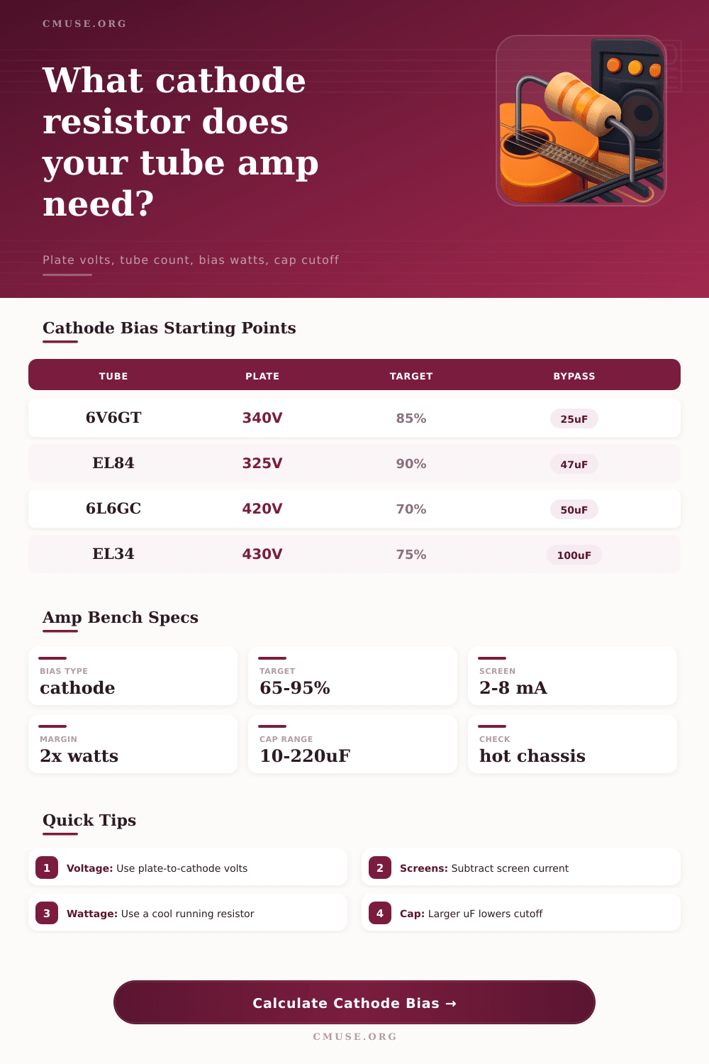
Once you enter your measured values and desired percentage dissipation, the calculator does math for you. No more searching through datasheets for curves that change depending on temperature and screen current. So first examine the plate voltage to ground. That’s the amount of raw potential energy with no drop across cathode resistor. An EL34 pair on 430 volts is not different than a pair of 6V6GTs running on 340 volts. More voltage mean you need a firmer approach to biasing to keep plate dissipation in check. This is where type of tube becomes part of the equation. An EL84 can only takes so much heat before it degrades while a KT88 can handle more heat before it starts burning out. Those max ratings become anchor points for the tool.
Then you choose what percentage you want to run, usually anywhere from seventy to ninety percent for guitar amps. This gives you some headroom while keeping output stage from being cooked. Using more may sound punchy at first but it shortens life of the tubes a lot.
Don’t overlook how much power the screen use. Most discussion about bias focus on plate current, so it’s tempting to get caught up only considering this parameter. Remember, however, electrons are flowing from cathode to both the screen grid and the plate. Failure to consider screen draw result in under-estimating overall cathode current. Consequently, you end up with a resistor whose value is too great. Your resulting bias will be less than desired. To ensure accuracy, estimate or measure screen draw. This tweak guarantee your final resistor selection will give targeted dissipation, not leave you wondering.
There’s another twist with the addition of the bypass capacitor. It grounds AC signals at the cathode while maintaining DC bias. Basically it remove any negative feedback for these frequencies. To tighten up the low end again, add some more feedback and use smaller caps. As the cap value increases it lower the cutoff frequency bringing more bass response and sag back into the tone. And if you want less low end increase the resistor size. The calculator will estimate what the cutoff frequency is going to be given your selected component values. This lets you see how changing resistance will affect the tone before you even solder anything down. You may find that using a 220 ohm resistor makes the 50uF seem loose whereas a 470 does not. Finding the right balance between component is the trick.
There is no margin for safety. Cathode resistors do actualy dissipate real heat and can be several watts apiece in a pair configuration. Carbon composition resistors will move off-value when hot, and if run too hard they’ll go completely open. Ceramic wirewound types withstand higher temps, but hold charge that is dangerous to release without proper discharge. Get your resistor wattage rating significantly higher than the amount you calculate it will use. And if there’s room, double it. It is cheap insurance against random failure on long nights or ear-shattering jams.
Lastly, warm ’em up and then check it out with a multimeter. As tubes warms up, their qualities can shift. What’s spot-on when first checked may have drifted by in twenty minutes. Cathode bias takes iteration. You do the math, you assemble, you test, you fiddle. There’s no magic perfect number on your sheet of paper. Finding that sweet spot where the tubes runs cool without burning out, that’s what maintains your rig over decades.