Humbucker DC Resistance Calculator
Estimate pickup DC resistance from two coil turn counts, magnet-wire gauge, mean turn length, temperature coefficient, wiring mode, split choice, target kOhms, and output balance.
Resistance Breakdown
| Mode | Calculated DCR | Loaded Meter Reading | Use Case |
|---|---|---|---|
| Run the calculator to populate wiring results. | |||
| Coil | Turns | Wire Length | R at 20 C | R at Temp |
|---|---|---|---|---|
| Run the calculator to populate coil details. | ||||
| Gauge | Ohms per 1000 ft | Typical Pickup Use | Planning Note |
|---|---|---|---|
| 38 AWG | 648 ohms | Low turn-count experimental coils | Thicker wire gives lower DCR for the same turns. |
| 40 AWG | 1,049 ohms | Large format or low resistance coils | Useful when the bobbin has enough window space. |
| 42 AWG | 1,659 ohms | Classic humbucker and PAF style winds | A common baseline for 7 to 9 kOhm humbuckers. |
| 43 AWG | 2,143 ohms | Hotter bridge and compact bobbin winds | Raises DCR without needing as much coil space. |
| 44 AWG | 2,593 ohms | Rails, stacked coils, very hot targets | Small changes in turn count move DCR quickly. |
| 45 AWG | 3,351 ohms | Special high-DCR compact designs | Fragile wire; keep tension and traverse conservative. |
| Reference | Typical Range | What It Means | Bench Caution |
|---|---|---|---|
| Vintage neck | 7.0 to 8.0 kOhms | Clearer series reading with moderate turns | Temperature can shift the meter by more than 0.1 kOhm. |
| Vintage bridge | 8.0 to 9.2 kOhms | Slightly higher turn count for bridge balance | Match target at a stated room temperature. |
| Hot bridge | 12 to 16 kOhms | Often 43 AWG or thinner wire | DCR alone does not equal output or inductance. |
| Parallel wiring | 1.8 to 4.5 kOhms | Both coils active with lower measured resistance | A low number can still be full humbucking. |
| Preset | Gauge | Coil Turns | Best Reading | Balance Goal |
|---|---|---|---|---|
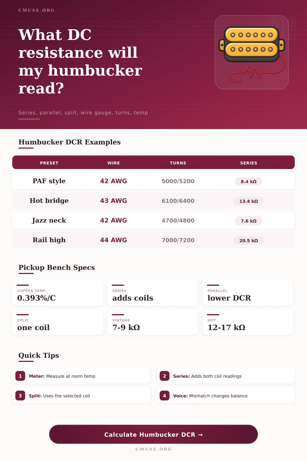
| Vintage PAF Neck | 42 AWG | 4,850 / 4,950 | Series around 7.9 kOhms | Nearly even coil voice |
| Vintage PAF Bridge | 42 AWG | 5,000 / 5,200 | Series around 8.4 kOhms | Slight screw emphasis |
| Modern Hot Bridge | 43 AWG | 6,100 / 6,400 | Series around 13.4 kOhms | Controlled mismatch |
| High Output Rail | 44 AWG | 7,000 / 7,200 | Series around 20 kOhms | Compact high DCR design |
DC resistance is simply a measurement of wire length and thickness… Not tone, but it’s a static snapshot of a coil of copper wrapped around steel that tells you precious little about how it sounds. That said, DC resistance are the one universal shorthand we have for describing pickups. While every winding shop obsesses over its number, most guitarists can’t tell you what’s going on.
When you hear them ask for a seven kiloohm neck pickup, they’re really asking for a certain level of predictability regarding inductance and a particular window space occupancy, although they can’t often explain what those things mean. Once you input your wire gauges and turn counts into this handy-dandy calculator, it do all the tricky math. This saves you the guesswork about how small gauge variations or other environmental factors like temperature might throw off your final number.
Why DC Resistance Matters
What they really should of get into is how things work physically with that bobbin. For example: copper resistance change based on temperature, which means it will change almost four-tenths of a percent for each degree celsius increase. This is significant because a pickup that reads X units at room temp first thing in the morning may be several units different then the very same pickup after sitting in a hot workshop for awhile. Two degrees can send you from under spec to exactly where you want to be for a vintage PAF spec.
While it’s small stuff, it cause folks to scratch their heads as to why the numbers don’t seem to add up between the bench and the real world. Most builders figure this out the hard way…they wind something down to a specific number only to have meter disagree an hour later because the heater in the shop turned on.
The gauge of the wire determine how much resistance it creates per inch of length. This also affects how many turns will fit within the window space. Because thinner gauges pack more turns inside the same physical space, they ramp up their DC resistance at a quicker rate, but don’t need an insanely large amount of coil to do so. That’s why high output rails commonly employ thin wire even when their overall sizes is comparable to vintage designs.
Those different gauges also factor into the calculator. It uses standard ohms-per-thousand-feet values so you can compare a traditional 42 AWG wind to a moddern 44 AWG wind on an apples-to-apples basis. As you’ll notice above, thinner wire increases the rate at which resistance grows. This helps you determine whether you should cut back on your turn count to avoid filling the window too soon.
Theory meets messy reality with a mismatch between coils. In practice, perfectly matched coil of resistance are uncommon, and perhaps undesirable. For most genres, a small difference in DC resistance usually correspond with a satisfying mismatch in midrange response where the neck remains clear and the bridge pickup have its distinctive bite. Sometimes, when both coils read out as being equal, the resulting tone can seem too balanced, too sterile, even characterless.
By showing how far apart your screw/coil and slug/coils are from each other (shown as a percentage), the tool help you see if your mismatch is in that sweet spot for your desired genre. You’re aiming for just enough difference to make it interesting; not too different than cause total loss of hum cancellation.
The way that resistance plays within your guitar’s electronics is entirely dependent on the wiring mode. Standard series wiring combine the resistance of each coil, resulting in a greater impedance load that work great with traditional fifty-thousand-ohm pots. When wired in parallel, the total DC resistance drop. This reduces the RC time constant created between the potentiometer and any cable capacitance, making the tone brighter. A split to one coil separates its resistance from the other, essentially transforming a humbucker into a single-coil model.
This calculator lays all those examples out side-by-side. You can visually compare differences between different wiring modes and understand exactly what kind of electrical load they represent, without having to rewire the guitar at all. You’ll be able to guess beforehand if your parallel wiring might sound extra bright, or if it might turn out too thin and nasal.
In the end, DC resistance is not an audio equalizer; it’s a metric for planning. It indicates that the coil balance is within reason, the temperature was controlled, and the wire fit. But it does not indicate the strength of the magnetic field, how saturated the core material may be, nor the small differences in winding tension which realy determine voice.
These are the numbers you use to create a batch of pickups consistently, rather than to promise a certain sound. First build something predictable and leave the rest up to your ears. Stop thinking of the multimeter as a tone knob and start seeing it as a quality control stamp. Once you do, winding stops being a chase after ghosts and becomes a way to create dependable instruments for players who know what they want.