Comb Filter Frequency Calculator
Convert delay time, acoustic path difference, or sample offset into comb spacing, first notch, first peak, and band counts.
🎧 Real Audio Presets
🎚 Comb Filter Inputs
📊 Frequency Spec Grid
🎼 Notch and Peak Series
| Order | Notch Frequency | Peak Frequency | Band Note |
|---|---|---|---|
| 1 | 500 Hz | 1000 Hz | Low mid |
| 2 | 1500 Hz | 2000 Hz | Presence |
| 3 | 2500 Hz | 3000 Hz | Presence |
| 4 | 3500 Hz | 4000 Hz | Upper mid |
📏 Delay to Path Reference
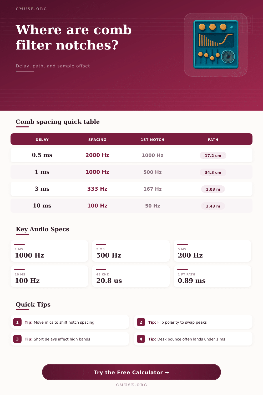
| Delay | Spacing | Normal First Notch | Path Difference |
|---|---|---|---|
| 0.25 ms | 4000 Hz | 2000 Hz | 8.6 cm / 3.4 in |
| 0.50 ms | 2000 Hz | 1000 Hz | 17.2 cm / 6.8 in |
| 1.00 ms | 1000 Hz | 500 Hz | 34.3 cm / 13.5 in |
| 2.00 ms | 500 Hz | 250 Hz | 68.6 cm / 27.0 in |
| 5.00 ms | 200 Hz | 100 Hz | 1.72 m / 5.63 ft |
| 10.00 ms | 100 Hz | 50 Hz | 3.43 m / 11.25 ft |
🔀 Comb Type Comparison
| Type | First Notch | First Peak | Common Audio Case |
|---|---|---|---|
| Normal summed delay | 1 / 2T | 1 / T | Reflection added without polarity flip |
| Inverted reflection | 1 / T | 1 / 2T | Polarity-flipped mic or boundary path |
| Short sample slip | High frequency | High frequency | DAW clip alignment by samples |
| Long slap blend | Low frequency | Low frequency | Audible echo color or flanging sweep |
🎤 Common Studio Scenarios
| Scenario | Typical Offset | Comb Spacing | What Moves |
|---|---|---|---|
| Desk bounce to vocal mic | 0.6 to 1.2 ms | 833 to 1667 Hz | Desk height and mic angle |
| Two guitar cabinet mics | 0.1 to 0.8 ms | 1250 to 10000 Hz | Capsule distance and polarity |
| Floor reflection near speaker | 3 to 8 ms | 125 to 333 Hz | Speaker height and listener distance |
| Artificial double tracking | 8 to 25 ms | 40 to 125 Hz | Delay time and wet level |
| Flanger delay range | 1 to 10 ms | 100 to 1000 Hz | Modulated delay time |
When two version of the same sound reach the listener at different time, comb filtering occurs. Comb filtering can cause certain frequencies to become louder than other and some frequencies to almost complete dissapear. These type of filters have peaks and notches in the sound’s frequency analysis that look similar to a comb, hence the name of this type of filter.
A vocal can sound hollowly when comb filtering occurs or a guitar player may notice that their guitar recordings lose focus. Using a calculator, the engineer can determine the locations of these notches if the engineer know the delay time, the path difference, or the sample offset of the sound that is being reflected. Path difference can be create, for example, if a microphone is placed on a cabinet and reflected off of a desk or if the sound from the microphone is reflected off of a boundary.
What Causes Comb Filtering and How to Fix It
Sample offset can be created if the audio engineer use tools like a digital audio workstation to move a sample within its recording. The calculator will display the spacing between the notches in the sound and the location of the first notch, allowing the engineer to determine if the spacing is important to the music. The spacing between the notches are related to the length of the delay between the two versions of the same sound.
A long delay between the two sound sources will create notches that is more closer together in frequency than if the delay between the two signals was short. A short delay will have notches within the high frequencies of the sound only affecting the brightness and air of the sound. A long delay will impact the fundamental tone of the sound, such as the vocal or instrument that is being record.
If a microphone is moved, the path length between the sound source and the microphone will change, thus changing the focus of the song being recorded. The polarity of the signal can also impact the way that the comb filter work. If the signal that is reflected is inverted, the peaks and notches will be swapped.
A dip in frequency will become a boost in frequency and a boost will become a dip in frequency. An inverted signal can be created if the microphone that is picking up the sound is wired out of phase or if the reflected sound come from a boundary. Using the calculator, the engineer can view the difference between the non-inverted and inverted signals.
Many room can complicate the calculation of the locations of the notches created by a comb filter. The absorption rate of the room can change depending on the frequency of the sound that is reflected. The distance of the sound from the boundary will also change the level of the sound that is reflected.
Yet knowing the theoretical location of the notches can still help engineers to know where to start listening for the sound. For example, if the first notch is calculated to occur at around 500 Hz in a vocal recording, the engineer will know that the vocal sounds thin due to this notch in the vocal. There are many scenario in the recording studio in which comb filtering can occur.
For instance, if the vocal track’s microphone is placed above the desk upon which the vocal is being recorded, the reflected signal from that desk will have a path difference between the vocal that is picked up direct by the microphone and the reflected signal from the desk. The delay between the vocal and the reflected signal will have notches between 800 and 1600 Hz, which is the presence range of vocal frequencies. If the engineer move the vocal microphone, the path length between the vocal and the microphone will change.
This same parameter is used for the placement of overhead microphones for drum or even microphones placed near guitar cabinets. In the digital age, comb filtering can be created using digital sample offset. For instance, if an engineer moves a vocal track that is being doubled in time by twenty samples at a sample rate of 48 kHz, the vocal will have a delay of 0.4 millisecond.
This will create notches in the high frequencies of the vocal that listeners may describe as “phasey.” At a sample rate of 96 kHz, twenty samples will only take up half the time of the vocal delay, thus moving the notches even higher in the frequency range. The sample offset can be entered into the calculator so that the engineer can determine whether the sample offset is helping the vocal or if the comb filter created by the sample offset is fighting the vocal. If the delay created by the comb filter is longer than a few milliseconds, the effect of the notches will be more widespread throughout the vocal.
For instance, if the vocal is doubled at a delay of 15 or 20 milliseconds, the notches will be at 50 to 70 Hz. Such a delay will make the vocal sound distant yet the delay is too long for humans to hear the reflected vocal echo. The same effect can be used to create a flanger effect in which the notches will move through the midrange of the vocal as the delay is swept from 1 to 10 milliseconds.
Comb filtering is a natural occurrence in creating a vocal track yet it can be used to both help and fight the sound that is being create. Understanding how the comb filter works allow engineers to have more control over it. Furthermore, understanding the ways that engineers can alter the filter allow the engineers to have control over the filter.
The notch can be controlled by placement, polarity or even absorption. The comb filter calculator will allow engineers to make there decisions based on listening to the vocal rather than performing the arithmetic to determine whether the placement, polarity or absorption settings create the filter.