Cable Run Voltage Drop Calculator
Estimate stage feeder and branch-circuit voltage loss from current, one-way cable length, AWG or mm2 conductor size, copper or aluminum material, supply voltage, phase, power factor, and target drop.
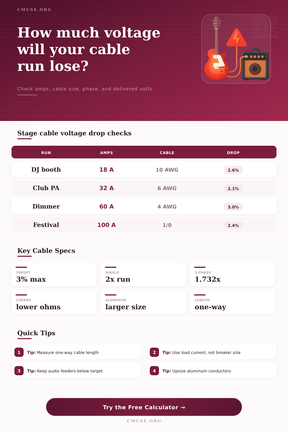
One-way length model: Pick a familiar production run, then adjust the measured load current, cable size, material, and phase to match the actual feeder or extension cable.
Calculation Breakdown
Conductor Area
Ohm / 1000 ft
Max Target Length
Max Target Current
| Conductor size | Area | Copper ohm/1000 ft | Aluminum ohm/1000 ft | Stage use note |
|---|---|---|---|---|
| 12 AWG | 3.31 mm2 | 1.93 | 3.18 | Short 15 to 20 A branch runs and light backline. |
| 10 AWG | 5.26 mm2 | 1.21 | 2.00 | Long extension cables, powered speakers, DJ booths. |
| 8 AWG | 8.37 mm2 | 0.764 | 1.26 | Small feeder, subwoofer power, FOH utility run. |
| 6 AWG | 13.3 mm2 | 0.491 | 0.808 | Common 50 to 60 A stage branch or feeder cable. |
| 4 AWG | 21.2 mm2 | 0.308 | 0.508 | Longer dimmer, lighting, or small distro feed. |
| 2 AWG | 33.6 mm2 | 0.194 | 0.319 | Higher-current feeder where voltage stability matters. |
| 1/0 AWG | 53.5 mm2 | 0.122 | 0.201 | Portable feeder for larger stages and outdoor runs. |
| 4/0 AWG | 107 mm2 | 0.0608 | 0.100 | Main feeder tails, large distros, long production runs. |
| System | Multiplier | Voltage basis | Formula term | Best stage use |
|---|---|---|---|---|
| Single phase AC | 2.000 | Line voltage | I x L x 2 x Z / 1000 | 120 V branch circuits, split-phase feeders, extension runs. |
| Three phase AC | 1.732 | Line-to-line | I x L x 1.732 x Z / 1000 | 208 V, 400 V, or 480 V stage distros and generator feeds. |
| DC two-wire | 2.000 | DC bus voltage | I x L x 2 x R / 1000 | Battery, LED tape, control power, and low-voltage audio gear. |
| AC with power factor | By phase | RMS voltage | R x PF + X x sin angle | Powered PA, dimmers, LED drivers, motors, and mixed loads. |
| Drop range | Planning status | Audio impact | Lighting impact | Action |
|---|---|---|---|---|
| 0 to 2% | Excellent | Strong headroom for powered PA and amp racks. | Stable output for LEDs, movers, and control gear. | Good for critical feeders and long show days. |
| 2 to 3% | Good | Common target for live audio branch circuits. | Usually acceptable for modern LED fixtures. | Verify with actual load current during soundcheck. |
| 3 to 5% | Watch | May reduce amplifier rail headroom on peaks. | Can dim tungsten and stress supplies at high output. | Shorten cable, split loads, or upsize conductor. |
| Over 5% | High | Risk of low-voltage behavior under bass-heavy load. | Greater risk for fixture faults and unstable dimming. | Rework feeder plan before relying on the run. |
| Preset | Typical run | Current | Cable choice | Planning note |
|---|---|---|---|---|
| Coffeehouse FOH | 75 ft / 23 m | 12 A | 12 AWG copper | Short branch run for mixer, small PA, and light backline. |
| DJ Booth Feed | 100 ft / 30 m | 18 A | 10 AWG copper | Upsized cable helps keep powered tops and subs lively. |
| Theater Dimmer Run | 175 ft / 53 m | 60 A | 4 AWG copper | Longer lighting feed benefits from a tighter drop target. |
| Festival Side Stage | 250 ft / 76 m | 100 A | 1/0 copper | Three phase feeder run where voltage stability matters. |
| Arena Front Fill | 300 ft / 91 m | 45 A | 2 AWG copper | Long audio feeder where oversized conductors protect headroom. |
When you run an electrical cables to power your show, the voltage at the far end of that cable will be more lower than the voltage at the power source. The resistance of the conductor will cause some of the voltage from the power supply to be lost as heat before it can reach the load in your show. The voltage drop will be small with a short length of cable with a low current draw, but will be higher with long cable runs across the festival or theater.
Because both amplifier and lights recieve less voltage from the power distribution system, they will not perform as good as when they are first loaded into the show. The current that the cable will carry is the most important variable in calculating voltage drop. While many will tell you to use the rating of the circuit breaker that protect the circuit to determine current, this is incorrect.
Voltage Drop in Stage Cables and How to Fix It
Circuit breakers are rated at higher currents than the equipment they protect. The current that you should use in your calculations is the current that the equipment draw when it is running at full power. Current draw can be found from a power draw sheet or a clamp meter.
Once you have determined the current that the equipment will draw, determine the distance that the current must travel in the cable, and the conductor that will be used. You should measure the length of the cable in one direction from the power source to the equipment. The longer the distance that the current has to travel in the conductor, the greater the voltage drop that will occur unless the cross-section of the wire are increased.
The material of the conductor will impact the resistance of the cable. Copper has a lower resistance than aluminum of the same size conductor, so most stage electrical cables is made of copper. Aluminum is light and cheap, but if you use aluminum, the conductor size must be increased to compensate.
The resistance of the conductor will also change according to the temperature of the conductor. Higher temperature will increase the resistance of the conductor. However, the change in resistance with temperature is usualy modest so that it has little impact on the voltage drop in most case.
The configuration of the three-phase power can impact the equation for calculating voltage drop. For three phase power, 1.732 is the multiplier for voltage drop, whereas 2 is used for single-phase power. The advantage of three-phase power are lost if the phases are unbalanced, so you should measure each phase leg for voltage.
The power factor will also impact voltage drop. Because motors, dimmers, and lighting controls can cause the current to be out of phase with the voltage, the power factor can increase voltage drop. Voltage drop calculations based solely off resistance will therefore be too low.
The voltage drop that is determined as a percentage of the supply voltage will be used to determine what level of voltage drop is acceptable for your lighting or sound equipment. Most audio and lighting technicians will accept a voltage drop of three percent or less in their main power feeders. A three percent drop will ensure that amplifier power rails are stable and LED light do not flicker.
For voltage drops between three and five percent, close monitoring of the voltage can occur. For voltage drops of five percent or more, you should shorten the cable, create a parallel run, or increase the size of the cable prior to the start of the show. The calculator will provide the arithmetic for voltage drop, voltage at the load, power lost as heat, and the maximum current for that cable size within your target voltage drop percentage.
These calculation will allow you to determine if a second run of the same cable should be created in parallel, or if the cable should be changed to a larger size. The resistance table will show the resistance for common sizes of wire in copper or aluminum. Voltage drop issues usualy emerge during load-in.
Cable runs that are safe for lighting and powering effects for small stages may fail when LED walls and monitors is added to the lighting layout. The solutions for voltage drop at load-in include measuring the current draw of the equipment, shortening the cable run, or replacing one long cable with two shorter cables. These mathematical calculations will reveal the same outcome as the voltage meters.
Voltage drop should of been considered in the planning of the show. If the length of the run, the load, and the available sizes of cable are known prior to beginning to setup the show, the correct conductor can be selected. If the conductor is selected correctly the first time, it will avoid the need to change cables between sound check and the start of the show.
Using the correct conductor will allow the audio and lighting to remain the same from the first cue to the last cue in the show.