Band Pass Filter Cutoff Frequency Calculator
Calculate lower and upper cutoff points, center frequency, bandwidth, Q, octave width, slope, tolerance spread, and sample-rate headroom for audio EQ, crossovers, synth filters, and measurement work.
🎛Named EQ and Crossover Presets
⚙Band-Pass Inputs
📊Current Filter Spec Grid
📐Band-Pass Formula Table
| Quantity | Formula | What It Means | Audio Use |
|---|---|---|---|
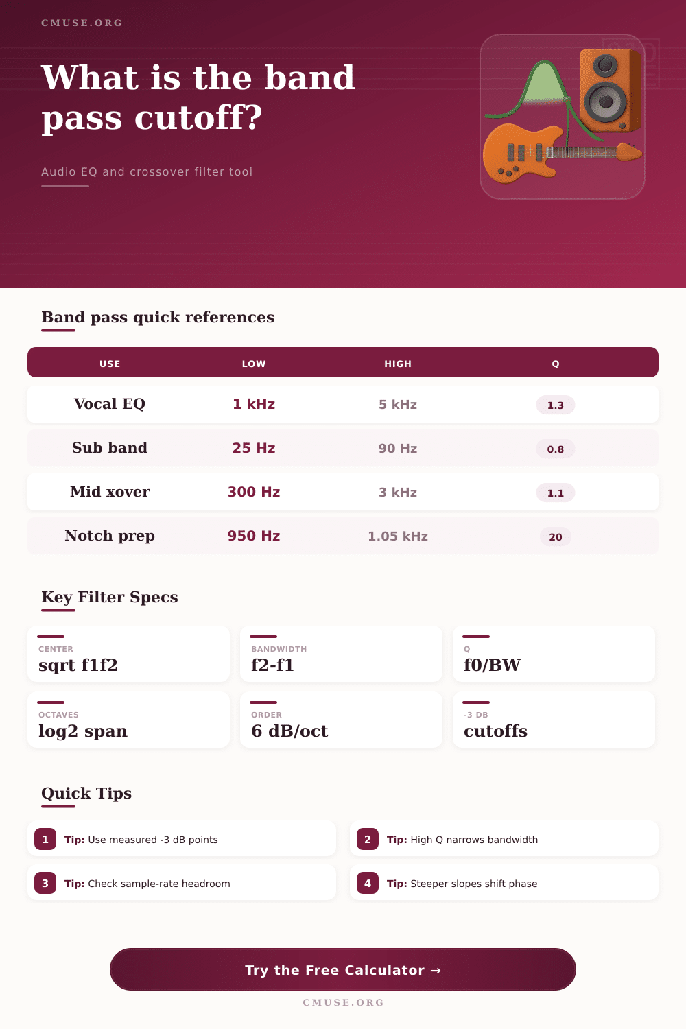
| Center frequency | f0 = sqrt(f1 x f2) | Geometric center of the pass band | EQ frequency, crossover mid-band reference |
| Bandwidth | BW = f2 - f1 | Frequency span between cutoff points | How much spectrum passes through |
| Quality factor | Q = f0 / BW | Narrowness or selectivity of the filter | Parametric EQ Q, resonant filter shape |
| Octave width | N = log2(f2 / f1) | Musical width of the band | Compare broad tone bands and narrow notches |
| Slope per side | 6 x order dB/oct | Approximate skirt steepness | Crossover roll-off and isolation planning |
🎧Common Audio Band-Pass Ranges
| Band or Task | Typical Low Cut | Typical High Cut | Approx Q | Practical Note |
|---|---|---|---|---|
| Subwoofer band | 20 to 35 Hz | 70 to 120 Hz | 0.6 to 1.0 | Protects excursion below tuning and limits upper bass bleed. |
| Telephone voice | 300 Hz | 3.4 kHz | 0.7 | Classic intelligibility band with limited bass and air. |
| Vocal presence EQ | 1 kHz | 5 kHz | 0.5 to 1.5 | Broad presence bands sound more natural than very narrow boosts. |
| Midrange crossover | 250 to 600 Hz | 2 to 5 kHz | 0.7 to 1.4 | Driver limits and acoustic slopes matter as much as electrical math. |
| Feedback search | Measured tone | Measured tone | 8 to 30 | Use a narrow band to identify the ring before applying a notch. |
⚖Q, Octave Width, and Slope Comparison
| Filter Character | Q Range | Octave Width | Slope Context | Best Fit |
|---|---|---|---|---|
| Very broad tone band | 0.4 to 0.8 | 2.0 to 3.5 oct | Gentle skirts often enough | Musical shaping, wide mix moves |
| Standard EQ bell | 0.8 to 2.0 | 0.7 to 2.0 oct | Moderate slopes keep phase mild | Vocals, guitars, drums, room correction |
| Focused resonance | 2.0 to 8.0 | 0.18 to 0.7 oct | Steeper skirts isolate the band | Synth filters, resonators, special effects |
| Surgical or measurement | 8.0 and up | Under 0.18 oct | Check ringing and latency | Feedback hunting, lab bands, narrow tests |
📋Preset Comparison Table
| Preset | Low Cutoff | High Cutoff | Order | Use Case |
|---|---|---|---|---|
| Vocal Presence Bell | 1 kHz | 5 kHz | 2nd | Presence shaping without full-band harshness. |
| Subwoofer Pass Band | 25 Hz | 90 Hz | 4th | Protects lows and keeps upper bass controlled. |
| 3-Way Midrange Xover | 350 Hz | 3.2 kHz | 4th | Starting point for mid driver band limits. |
| Guitar Wah Peak | 650 Hz | 1.7 kHz | 2nd | Nasal, resonant guitar filter focus. |
| Radio IF Narrow Band | 452 kHz | 458 kHz | 6th | Very selective communications-style band. |
A band pass filter is a tool used in audio work to allow certain frequencies to pass through while pushing other frequencies away. A person often uses a band pass filter when a person need to carve space for a vocal or when a person need to place limits on a speaker driver. A band pass filter have a lower cutoff and an upper cutoff frequency.
These frequencies indicate the frequencies at which the signal is dropped to half of its power. Thus, the portion of the signal that falls within the range of the lower cutoff and the upper cutoff will pass through the band pass filter. Thus, the lower and upper cutoff frequencies of a band pass filter work to determine the center frequency, bandwidth, and selectivity of the filter.
How a Band Pass Filter Works
The mathematical relationship between these three components is, therefore, importance to the function of the band pass filter. The center frequency of a band pass filter sits at the geometric mean of the lower cutoff and the upper cutoff frequencies. This center frequency does not sit at the arithmetic mean (or average) of the two frequencies.
The bandwidth is the difference between the upper and the lower cutoff frequencies, which indicate the portion of the signal that passes through the band pass filter (as opposed to the portion that the band pass filter gets rejected). The Q factor is calculated as the ratio of the center frequency to the bandwidth. If a person leaves the gain of the band pass filter unchecked, high values of the Q factor will result in the band pass filter ringing or clipping.
The order of the band pass filter help to determine at what rate the frequencies outside of the passband of the filter are rejected. First order filters reject the frequencies outside of the passband at a rate of 6 decibels per octave. Higher order filters reject the frequencies outside of the passband at steeper rates.
Higher order filters are useful for application where it is important to provide isolation between speakers’ drivers or between a microphone and a feedback frequency. Higher order filters, however, introduce more delay than first order filters. No component is perfect, and rooms have different characteristics than the ideal environment indicated in the calculations of a band pass filter.
For example, the tolerance of the components can change the cutoff frequencies of the band pass filter. The temperature of the components can alter the values of resistors within a filter. The impedance of a speaker driver can change with the level of the signal being played and the frequency of that signal.
Additionally, the upper cutoff frequency of a digital band pass filter should not be set to a frequency that is too close to half the sample rate of the audio file; if it is, the digital filter will behave differently than the calculations indicate for the filter. Depending upon the application of the band pass filter, the same filter can be used to accomplish different tasks. For example, a vocal presence band pass filter may be set between 1 kHz and 5 kHz.
A subwoofer band pass filter will be set to a narrower and lower range of frequencies to allow for larger excursion of the speaker driver while still allowing the fundamental frequency of the sound to pass through the speaker. A measurement band pass filter is used for analyzing rooms, and so the edges of the passband need to be consist from measurement to measurement. The calculator can calculate the values for the different tasks.
For instance, if a person selects the parameters of the band pass filter to be set to a certain value, the calculator can calculate the values for the other variables, such as the bandwidth and the Q factor. The calculator can also calculate the cutoff frequencies if the other variables are known. Another way to consider the band pass filter is in relation to the octave width of the filter.
Musicians are often more comfortable using this concept to describe a band pass filter rather than the more abstract concept of bandwidth. For example, a bandwidth of two octaves will feel broader than a bandwidth of half an octave. Extremely narrow bandwidths with high values of the Q factor can allow for the isolation of a single ringing mode within a speaker driver.
However, such narrow bandwidths may be more sensitive to tuning error. It should be noted that many people are unaware of this aspect of a band pass filter; their ear is far more sensitive to this issue than their measurement tools. The alignment of a speaker system will impact the way in which the band pass filter will behave.
For example, if the alignment is set to Butterworth, the magnitude response of the system will be as smooth as possible. A setting of Linkwitz-Riley alignment will allow the speakers to sum in a way that minimizes feedback at the crossover frequencies. A Bessel filter will allow for the smoothest possible phase response of the system.
However, a Bessel filter will have a less steep roll-off of the frequencies outside the passband of the band pass filter. A synthesizer patch may use a high value of the Q factor to allow for resonance within the filter. However, corrective EQ will work better at a more moderate value of the Q factor.
A person must make a decision regarding a band pass filter and its settings according to what a person is trying to protect and what a person is willing to lose when that protection is made. For example, when making a crossover between speakers, the acoustic response of the crossover will be more important than the electrical response of that crossover. For feedback searches, the band pass filter should be narrow enough to find a feedback tone with the speakers, but it should not be so narrow that it misses that tone if the level of the sound change.
For creative effects, the band pass filter can be pushed to extremes since the goal is to colorate the sound. Once the cutoff frequencies have been set, the remaining work is to listen to the sound that is created by the band pass filter and to adjust the parameters of the filter as necessary. Adjustments to the center frequency of the band pass filter are generally more important than adjustments to the Q factor of the band pass filter once the band pass filter has been set to a relatively narrow range of frequencies.
The gain of the band pass filter impacts both the center frequency and the Q factor; a narrow band pass filter with high gain will overload the system. Thus, while the calculator can provide the appropriate settings for a band pass filter, a person using the system will establish the final settings of the parameters through the sound that is heard. Calculated values will not always be the final answers for the parameters of a band pass filter.
It is always possible to measure the acoustic edges of the passband of a band pass filter and to compare those measurements to the calculated (electrical) values of the passband. It is also important to allow for some margin for error in the measurements of time and frequency due to the fact that components wear with use and that the temperature of the components can change as the system is in use. Thus, allowing for these factor will allow the band pass filter to perform as intended.