Low Pass Filter Cutoff Frequency Calculator
Calculate RC and RL low-pass cutoff frequency, required capacitor or inductor value, filter order slope, -3 dB behavior, and component tolerance range for audio crossover and synthesizer work.
🎛Named Audio Low-Pass Presets
⚙Filter Inputs
📊Live Filter Spec Grid
🔎RC vs RL Comparison Grid
RC Line Low Pass
RL Speaker Low Pass
Cascaded Poles
Crossover Target
📚Low Pass Formula Reference
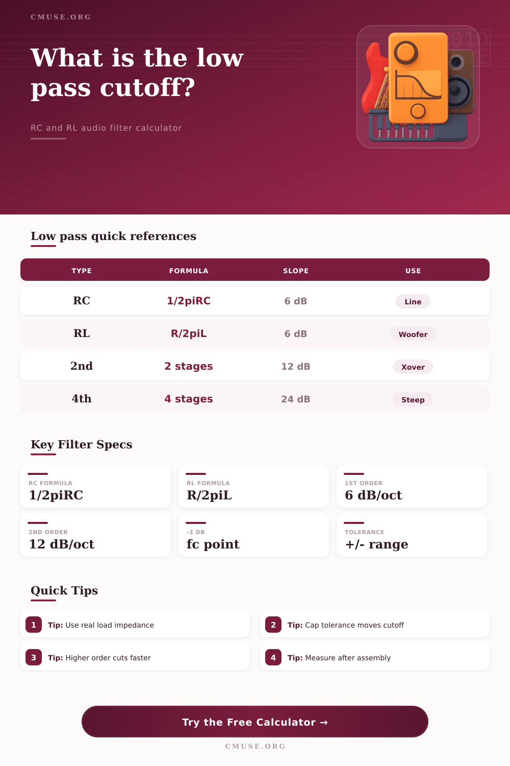
| Filter type | Cutoff formula | Required component | Audio use |
|---|---|---|---|
| RC one-pole low pass | fc = 1 / (2 x pi x R x C) | C = 1 / (2 x pi x R x fc) | Line-level tone shaping, guitar tone circuits, synth smoothing |
| RL one-pole low pass | fc = R / (2 x pi x L) | L = R / (2 x pi x fc) | Woofer series coil, simple passive speaker roll-off |
| Cascaded RC or active poles | Nominal pole fc per stage | Repeat or scale sections | Higher-order synth filters, anti-alias guards, active crossovers |
| Acoustic crossover target | Electrical plus driver response | Measure and adjust | Speaker crossover work where impedance and driver roll-off change the result |
🧮Common Component Reference
| Scenario | Example R or load | Example C or L | Approx cutoff |
|---|---|---|---|
| Guitar tone capacitor with 250 k pot at half region | 125 k ohms | 0.022 uF | About 58 Hz electrical corner, broader in real wiring |
| Synth RC smoothing after control source | 100 k ohms | 0.1 uF | About 15.9 Hz |
| Line-level gentle darkening filter | 10 k ohms | 4.7 nF | About 3.39 kHz |
| 8 ohm woofer first-order low pass | 8 ohms | 0.50 mH | About 2.55 kHz |
| 4 ohm subwoofer first-order low pass | 4 ohms | 8.0 mH | About 79.6 Hz |
📐Slope and Order Table
| Order | Poles | Nominal slope | Typical audio meaning |
|---|---|---|---|
| 1st order | 1 pole | 6 dB/oct or 20 dB/dec | Gentle phase behavior, shallow attenuation past cutoff |
| 2nd order | 2 poles | 12 dB/oct or 40 dB/dec | Common crossover starting point and active filter block |
| 3rd order | 3 poles | 18 dB/oct or 60 dB/dec | More separation with increased phase rotation |
| 4th order | 4 poles | 24 dB/oct or 80 dB/dec | Popular Linkwitz-Riley acoustic crossover target |
| 6th order | 6 poles | 36 dB/oct or 120 dB/dec | Very steep synthesis, DSP, or protection-style filtering |
🎼Preset and Spec Reference
📋Named Preset Comparison Table
| Preset | Topology | Target range | Primary design caution |
|---|---|---|---|
| Subwoofer 80 Hz RL | RL | Sub bass handoff | Driver impedance varies across frequency |
| Woofer 2.5 kHz RL | RL | Two-way woofer roll-off | Include baffle and cone breakup response |
| Synth Ladder 1.2 kHz RC | RC | Synth tone reference | Resonance and active stages change the curve |
| Guitar Tone Roll-Off | RC | Passive guitar darkening | Pickup, cable, and pot taper all interact |
| Tape Hiss Trim | RC | Bright noise reduction | Too low a cutoff removes vocal air |
| ADC Alias Guard | RC | High audio-band protection | One pole is not enough alone for hard alias rejection |
A low pass filter are a circuit component that can be placed between the signal and the next stage of the circuit. A low pass filter will allow low frequencies to pass through the component while it removes the high frequencys from an signal. The point at which the high frequencies are removed is referred to as a cutoff frequency, which can be calculated based off the mathematical relationship between the components of the circuit.
While a calculator can determine the mathematical relationship of the components, it cannot determine if the calculated values of the component will be apropiate for the circuit that is to be constructed. Depending upon the type of filter that is constructed, the resistance and capacitance of the circuit can have different role within the circuit. For instance, in an RC filter, the resistor can be placed in series with the circuit and the capacitor can be used to shunt the high frequencies to ground; in this case, either the resistance of the circuit or the capacitance of the circuit can impact the cutoff frequency.
How to use a low pass filter calculator
Similar to the RC filter, the RL filter can incorporate the inductor in the series portion of the circuit, and the load resistance can impact the rate at which the load filters the signal. Thus, both of these filter types indicate the process by which the reactive component of the circuit charges and discharges relative to the period of the signal. In addition to these definitions, the order of the filter can also impact the function of the low pass filter.
The order of the filter can determine the steepness of the roll-off of the signal; a single pole filter can roll off at a rate of six decibels per octave, and the gentle roll-off provided by a single pole filter may be all that is needed to remove noise from a circuit. A two-pole and a four-pole filter can provide a steeper roll-off of twelve and twenty-four decibels per octave, respectively; the increased steepness can allow for a more better separation of the signals from different types of driver within a speaker system. The downside to increasing the steepness of the roll-off is that there will be more phase rotation of the signal; the more phase rotation that occurs to the signal, the more difficult it may be to accurately predict the summed response of the speakers at the alignment point at which their sound energy combines.
The calculator can be used to determine the slope that will result from the order of the filter that is selected, and this information will help to indicate whether additional complexity to the circuit is required. Additionally, the tolerance of the components of the filter may also impact the performance of the low pass filter. For instance, if the filter includes a capacitor with a five percent tolerance of the calculated value of the component, it is possible that the actual capacitive reactance will shift five percent from the calculated value.
Such a shift within a stereo speaker system, for example, can lead to an imbalance between the left and right channels of the speakers, which the listener can hear. Thus, an alternative to using capacitors with five percent tolerance is to measure the components prior to soldering them to the circuit. Furthermore, the “load” of the circuit may behave differently than the resistors that are accounted for in the mathematical formulas for the low pass filter.
For instance, the impedance of a woofer increases as frequency decreases, guitar pickups can contain a resonant peak at a certain frequency, and the output stage of an operational amplifier can exhibit a certain amount of source resistance. These factor in the load of the circuit will shift the actual cutoff frequency of the signal away from the calculated cutoff frequency. Thus, another alternative to accounting for these varying load components is to build a prototype of the circuit to measure its response.
The load’s response can then be accounted for by adjusting the components of the circuit accordingly. Because the calculator for determining the components of a low pass filter can be used for various goals, the calculator is independent of those various goal. For instance, the calculator can be used to remove ultrasonic energy from an analog to digital converter; it can be used to remove hiss from a tape return device; or it can be used to change the tone of a guitar string.
In each of these cases, it is necessary to enter the frequency that is to be removed from the signal, and the resistance that the reactive component will encounter in the signal. Based upon these two entries, the calculator can determine the value of the reactive component that will place the cutoff frequency of the low pass filter at the desired location. The third setting for the calculator relates to the alignment of the filter.
For instance, alignment can be set to Butterworth, Bessel, or Linkwitz-Riley filters. Each of these settings will change the characteristics of the resulting filter; however, they will not impact the calculated value of the cutoff frequency. Another alternative to setting this parameter is that the various alignment settings will impact the text that the calculator provides for the reader, should they wish to scale the single RC filter stage to a higher order active filter stage.
The most common mistake with using the calculator to determine the required components for a low pass filter is treating the calculated frequency of the signal as the goal for that stage of the circuit. Instead, the calculated frequency should be treated as a starting point for constructing the circuit; once the circuit is constructed, some adjustments will likely be required to the frequency of the signal. By using the calculated frequency as a starting point, the adjustments to the components will be easier to make.
Thus, the calculator will ensure that the resulting low pass filter is successful in removing the unwanted energy from the signal, and ensuring that the low pass filter itself is not noticeable within the sound that is radiated by the speaker system.