Q-Value Calculator
Calculate quality factor, bandwidth, cutoff frequencies, damping ratio, octave bandwidth, and resonance behavior for audio EQ, filters, speaker ports, strings, rooms, and tuned resonators.
🎚Named Filter and Resonator Presets
⚙Q and Bandwidth Inputs
📌Q Interpretation Snapshot
📈Comparison and Spec Grid
📋Q Formula Reference Table
| Known values | Primary formula | Derived values | Best use |
|---|---|---|---|
| Center frequency and bandwidth | Q = f0 / BW | Cutoffs from constant-Q quadratic | Parametric EQ and bandpass design |
| Lower and upper cutoffs | Q = sqrt(f1 x f2) / (f2 - f1) | f0, bandwidth, octave width | Measured -3 dB points or plots |
| Damping ratio | Q = 1 / (2 x zeta) | Bandwidth = f0 / Q | Second-order resonators and control models |
| Octave bandwidth | Q = sqrt(r) / (r - 1), r = 2^octaves | Cutoffs around f0 | Musical EQ widths and analyzer settings |
🎧Typical Q Ranges by Filter or Resonator
| Application | Typical Q range | Typical octave width | Interpretation |
|---|---|---|---|
| Broad mastering EQ shelf-adjacent bell | 0.5 to 0.9 | 1.5 to 2.5 octaves | Subtle tonal contour rather than isolated correction. |
| General channel EQ bell | 1.0 to 2.0 | 0.7 to 1.4 octaves | Musical focus that still blends into nearby harmonics. |
| Problem resonance cut | 4 to 10 | 0.15 to 0.35 octave | Targets boxiness, ring, whistle, or static buildup. |
| Feedback notch | 8 to 30 | 0.05 to 0.22 octave | Narrow removal with less impact on nearby tone. |
| Speaker port or cavity tuning | 5 to 20 | 0.07 to 0.30 octave | Higher Q gives stronger tuning but more audible ringing. |
| Mechanical or plate mode | 15 to 80 | 0.02 to 0.10 octave | Light damping and long decay dominate the behavior. |
🎛Preset Planning Table
| Preset | Center frequency | Bandwidth or cutoffs | Starting interpretation |
|---|---|---|---|
| Vocal Presence EQ | 2.5 kHz | 1.8 kHz bandwidth | Moderate bell for intelligibility and forwardness. |
| Kick Drum Notch | 315 Hz | 70 Hz bandwidth | Narrow cut for boxy drum shell buildup. |
| Violin Body Air | 285 Hz | 0.28 octave width | Acoustic resonance around a body-air mode. |
| Guitar Wah Peak | 1.2 kHz | 250 Hz bandwidth | High-color resonant peak with obvious movement. |
| Speaker Port Tuning | 42 Hz | zeta 0.055 | Lightly damped enclosure tuning reference. |
| Feedback Trap | 6.3 kHz | 130 Hz bandwidth | Very narrow live-sound correction. |
| Crossover Bandpass | 1.6 kHz | 900 to 2800 Hz cutoffs | Band allocation for a driver or processing split. |
| AM IF Ceramic | 455 kHz | 10 kHz bandwidth | Highly selective communications-style filter. |
| Plate Reverb Mode | 740 Hz | zeta 0.018 | Light damping and lingering resonant decay. |
| Synth Resonant LPF | 980 Hz | 0.18 octave width | Musical resonance before self-oscillation territory. |
📐Cutoff, Damping, and Ringing Guide
| Q band | Damping ratio | Time behavior | Practical caution |
|---|---|---|---|
| 0.50 to 0.71 | 1.000 to 0.704 | Highly damped or maximally flat behavior. | Good for smooth tone shaping, not surgical removal. |
| 1 to 2 | 0.500 to 0.250 | Defined but controlled resonance. | Often a useful first move for musical EQ bells. |
| 3 to 8 | 0.167 to 0.063 | Clear narrow emphasis or cut. | Check that the problem frequency is stable. |
| 10 to 30 | 0.050 to 0.017 | Strong selectivity with audible stored energy. | High-Q boosts can ring; high-Q cuts can sound phasey. |
| 30 and above | Below 0.017 | Long decay, strong resonance, or tight filter skirt. | Use with measurements and verify off-axis behavior. |
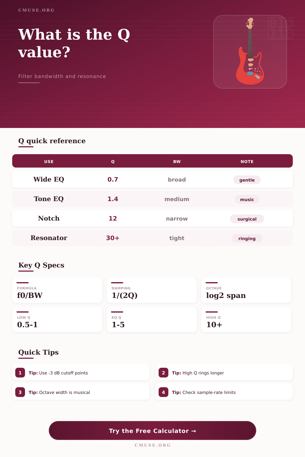
The Q-value of an filter is a measurement of the width of that filter. The Q-value determines the behaviors of a filter around the center frequency of that filter. Additionally, the Q-value determines whether the filter is to be wide or narrowely in its effect upon the audio spectrum.
If a person sets the Q-value to be low, then the filter will be wide in its effect upon the audio spectrum. Additionally, if a person sets the Q-value to be high, then the filter will be narrow in it’s effect upon the audio spectrum. A high Q-value are helpful for situations in which it is necessary to remove a specific frequency from the audio spectrum, yet still leave the frequencies near that specific frequency untouched.
What the Q-value of a filter is
The Q-value and the bandwidth of a filter is related to one another mathematically; the bandwidth and the Q-value are each other’s inverse, meaning that if a person knows either the bandwidth or the Q-value, they can calculate the other. The calculator provided can mathematically calculate the Q-value of a filter given either the bandwidth and the center frequency of the filter, or the two cutoff frequencies of that filter. Additionally, many people also calculates the Q-value of a filter using the damping ratio of that filter, which is often used in modeling mechanical systems.
This calculator accepts these various forms of input because the calculator is designed to help people move between different unit of measurement associated with filters; a mechanical engineer may set the damping ratio of the system, while a live sound technician may wish to work with the octave width of the filter, for instance. Thus, the calculator is designed to help a person in each of these different role to arrive at the same measurement. The calculated value for the Q-value of a filter is a theoretical measurement.
In the real world and in live sound engineering in particular, both instruments and room have resonances that can affect the sound in ways that are often not as described by the theoretical models of those instruments and rooms. For instance, both guitar and drum shell have resonances that often have a broad impact upon the sound that those instruments create. Thus, while the Q-value is a helpful measurement of the selectivity of a filter, the actual behavior of the system may drift from the theoretical model that calculates that selectivity.
As such, a person should of use the Q-value as a target for the behavior of the system, but use analysis software to ensure that the calculated Q-value is the appropriate setting for that system. Thus, while the calculator can provide a theoretical measurement of the width of the filter, it cannot provide any guarantee regarding whether the frequency will remain stable during the performance of the song. People can make mistake with the Q-value.
For instance, a Q-value of 4 may be relatively narrow for a kick drum, but it may be relatively broad for a cymbal. Additionally, the effect of the Q-value will change if the filter is boosting versus cutting the specific frequency. For instance, boosting at a high Q-value can cause the filter to ring at that frequency, and boost at a high Q-value can even lead to self-oscillation in digital system.
Cutting at a high Q-value will remove less surrounding material from the audio, but at a high Q-value can lead to phase issue. The sample rate at which the sound is sampled can also impact the behaviors of the digital filter in relation to the Q-value of that filter. If the upper cutoff frequency is near half the sampling frequency, the digital filter will not behave in the same way as the calculated mathematical model.
The calculator for the Q-value will indicate these situation so that a person can make a decision to either change the target frequency or the sample rate. Additionally, the Q-value of a filter is also related to the decay time of a filter. For instance, a narrow boost will have a high Q-value, and will ring for a longer period of time.
This may be either useful or problematic in live sound engineering, depending upon the live sound technicians goals. Similarly, if a technician would like to compare the decay time of different frequencies within the sound, they can use the damping ratio to formulate these time comparisons without having to rely upon ear to determine which frequencies have which decay times.