Crossover Inductor Calculator
Calculate passive speaker crossover inductor values, rounded coil sizes, DCR loss, tolerance span, reactance, and current headroom for woofer and midrange low-pass sections.
🎛 Quick Coil Presets
🔌 Inductor Inputs
Coil Selection Notes
📐 Alignment Coefficient Reference
| Alignment | Series Inductor Formula | Shunt Capacitor Formula | Use Case |
|---|---|---|---|
| 1st Order Butterworth | L = 0.159155 x Z / f henry | None for simple low-pass | Simple woofer rolloff with broad driver overlap |
| 2nd Order Linkwitz-Riley | L = 0.3183 x Z / f henry | C = 0.0796 / (Z x f) farad | -6 dB electrical target for LR acoustic design work |
| 2nd Order Butterworth | L = 0.2251 x Z / f henry | C = 0.1125 / (Z x f) farad | Classic -3 dB electrical corner |
| 2nd Order Bessel | L = 0.2756 x Z / f henry | C = 0.0912 / (Z x f) farad | Smoother phase target with a softer knee |
| 2nd Order Chebychev | L = 0.1592 x Z / f henry | C = 0.1592 / (Z x f) farad | Sharper electrical knee with more ripple tradeoff |
📋 Common First-Order Inductor Values
| Driver Load | 500 Hz | 1 kHz | 3 kHz |
|---|---|---|---|
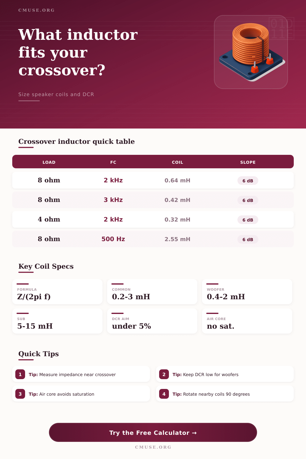
| 4 ohm woofer | 1.27 mH | 0.64 mH | 0.21 mH |
| 6 ohm woofer | 1.91 mH | 0.95 mH | 0.32 mH |
| 8 ohm woofer | 2.55 mH | 1.27 mH | 0.42 mH |
| 16 ohm guitar driver | 5.09 mH | 2.55 mH | 0.85 mH |
🧲 Coil Construction Comparison
| Coil Type | DCR Behavior | Current Behavior | Best Fit |
|---|---|---|---|
| Air core 20 AWG | Higher DCR on large values | No magnetic saturation | Small midrange and tweeter-adjacent coils |
| Air core 16 or 14 AWG | Lower DCR, larger physical size | No magnetic saturation | Woofer coils where resistance matters |
| Foil air core | Low DCR for its size | No core saturation | High-quality woofer and midbass filters |
| Laminated steel core | Very low DCR for high mH values | Can saturate at high current | Large subwoofer and low-mid coils |
| Ferrite or powdered iron | Compact with modest DCR | Needs current margin check | Space-limited passive networks |
🎧 Preset Scenario Grid
📊 Practical Crossover Notes
| Check | Target Range | Why It Matters | Calculator Output |
|---|---|---|---|
| DCR percentage | Under 5% is a good woofer target | Series resistance lowers level and changes damping | DCR percent and level drop |
| Reactance at Fc | About load impedance for 6 dB coils | Confirms the selected coefficient and crossover math | XL in ohms at crossover |
| Current margin | Above 1.5x reference current | Core coils and small wire can heat or saturate | RMS current and margin label |
| Rounded value shift | Keep frequency shift small when possible | Stocked coil values move the electrical crossover point | Actual Fc with rounded coil |
An inductor is one of the components that is use within a speaker crossover. An inductor blocks high frequencies from reaching the woofer, allowing only the low frequencies to pass through to the woofer. If the inductor has the wrong inductance value, the woofer will attempt to play the frequencies that the woofer are not designed to play; furthermore, the incorrect value of the inductor may cause the voice coil of the woofer to fail.
The inductor is used to create a clean handoff of the audio frequencies to the different speaker. When designing the inductor for the speaker, it is important to ensure that you dont use the impedance listed on the speaker driver itself. Speaker drivers may be labeled as having 8 ohm of impedance, but that impedance can vary throughout the audible frequency spectrum.
Inductors in Speaker Crossovers
Thus, it is important to measure the impedance of the driver at the crossover frequency; by using the measured impedance instead of the nominal impedance of the driver, the inductor will create the slope of frequencies that were intended for that driver. There is two main types of inductors that can be used within a speaker crossover: air core inductors and core inductors. Air core inductors do not include a magnetic material (core) within the inductor; for this reason, air core inductors will not saturate.
For these reasons, air core inductors will produce clean sound at any amount of power to the speaker. However, air core inductors will require a large amount of wire to achieve high inductance values. This amount of wire introduces high DC resistance (DCR) into the speaker.
High DCR levels will reduce the damping factor of the amplifier, making the bass of the speakers sound less controlledly. Core inductors are another type of inductor that can be used within the speaker. Core inductors include a magnetic material (such as ferrite or steel) within the inductor to achieve the necessary amount of inductance with less wire.
Because core inductors use less wire, they will have lower DC resistance (DCR) than air core inductors. Such low DCR is beneficial for subwoofers. However, if the power to the speakers is high enough, the magnetic material within the core can saturate.
When the core saturates, the sound will become distort. Thus, you must make a decision between the electrical efficiency of a core inductor versus the sonic purity of an air core inductor. A calculator can help determine the RMS current and headroom required of the inductor and the wire gauge needed to handle that many amount of power.
Inductors are also used to determine the slope of the crossover filter. A first order filter uses a single inductor in the crossover and allows for a 6 dB per octave roll off of the frequencies. More precise speakers will use second order alignments, such as Butterworth or Linkwitz Riley alignments.
Second order alignments use both an inductor and a capacitor to allow for more precisely roll off of the frequencies. Furthermore, you must also make a decision as to the alignment of the filter to prevent interference between the speakers within the crossover. For instance, Linkwitz Riley filters will keep the different speakers in phase with each other, preventing a dip in the frequency response of the speakers.
It is often difficult to find an inductor whose value is exactly the same as the calculated value for that driver. In these instance, using a standard inductor will create a shift in the crossover frequency. A shift in the crossover frequency is often acceptable; however, it can lead to a peak in the frequency response of the speakers if the system is required to have extreme accuracy in the sound that is created.
Thus, it is important to check the crossover frequency when using a rounded inductor value to prevent creating a frequency hole in the sound that is larger than that which was intended. Finally, another factor to consider in the design of the crossover is the placement of the inductors within the speaker. Because inductors act as magnets, it is possible for two inductors to couple magnetically with one another if they are placed too closely to each other.
Such coupling will alter the inductance values of the two inductors. Thus, to prevent this issue, you should keep the inductors within a crossover separated from each other, and should rotate them 90 degree relative to each other. By doing so, the accuracy of the inductance values will be maintain.