Crossover Capacitor Calculator
Calculate speaker crossover capacitor values, nearest standard parts, tolerance spread, reactance, and matching network estimates for tweeters, horns, and midrange high-pass sections.
🔊 Speaker Crossover Presets
🎛 Crossover Inputs
Network Parts and Stress Estimate
📊 Crossover Spec Snapshot
🧮 Spec Comparison Grid
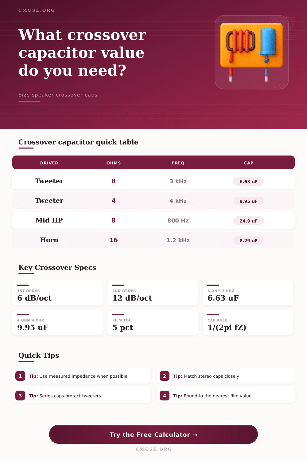
📐 Common First-Order Capacitor Values
| Target Frequency | 4 Ohm Driver | 6 Ohm Driver | 8 Ohm Driver | 16 Ohm Driver |
|---|---|---|---|---|
| 800 Hz midrange guard | 49.7 uF | 33.2 uF | 24.9 uF | 12.4 uF |
| 1.2 kHz horn entry | 33.2 uF | 22.1 uF | 16.6 uF | 8.29 uF |
| 2.5 kHz dome tweeter | 15.9 uF | 10.6 uF | 7.96 uF | 3.98 uF |
| 3 kHz common tweeter | 13.3 uF | 8.84 uF | 6.63 uF | 3.32 uF |
| 4.5 kHz car tweeter | 8.84 uF | 5.89 uF | 4.42 uF | 2.21 uF |
| 6 kHz super tweeter | 6.63 uF | 4.42 uF | 3.32 uF | 1.66 uF |
🔧 Standard Capacitor Rounding Reference
| Series | Typical Values in Each Decade | Best Use | Rounding Behavior |
|---|---|---|---|
| E12 | 1.0, 1.2, 1.5, 1.8, 2.2, 2.7, 3.3, 3.9, 4.7, 5.6, 6.8, 8.2 | Recaps and common stock | Wider steps, easy to source |
| E24 | Adds 1.1, 1.3, 1.6, 2.0, 2.4, 3.0, 3.6, 4.3, 5.1, 6.2, 7.5, 9.1 | Most audio film choices | Closer to target without odd pairing |
| E48 | Precision values with roughly 5 percent spacing | Matched stereo networks | Smallest frequency shift after rounding |
| Parallel Build | Ctotal = C1 + C2 + C3 | Fine tuning target values | Use two film caps to trim upward |
🎚 Crossover Network Comparison
| Network Choice | Cap Formula Used | Extra Part Estimate | Practical Reading |
|---|---|---|---|
| 1st order series cap | C = 1 / (2 pi f Z) | No inductor required | Gentle protection, more driver overlap |
| 2nd order Butterworth HP | C = 0.11254 / (f Z) | L = 0.22508 Z / f | Textbook 12 dB/oct electrical start |
| 2nd order LR estimate | C = 0.07958 / (f Z) | L = 0.31831 Z / f | Lower cap value and wider phase planning |
| Known capacitor check | f = coeff / (Z C) | Uses selected network | Helpful for identifying old crossover points |
🎵 Common Speaker Project Targets
| Project | Typical Impedance | Starting Frequency | Capacitor Target |
|---|---|---|---|
| Home hi-fi dome tweeter | 8 ohm | 2.5 to 3.5 kHz | 5.6 to 8.2 uF |
| Small car audio tweeter | 4 ohm | 3.5 to 5 kHz | 8.2 to 12 uF |
| PA compression driver | 8 ohm | 1.2 to 2 kHz | 10 to 16 uF first-order |
| Vintage cone tweeter | 6 to 8 ohm | 3 to 5 kHz | 3.3 to 8.2 uF |
| Midrange high-pass guard | 8 ohm | 500 to 900 Hz | 22 to 39 uF |
A crossover is an electrical circuit that are used to manage the frequencies that go to each of the specific speaker driver. A crossover is necessary to prevent high-frequency speaker, such as tweeters, from receiving low-frequency signals that can damage the voice coil of that tweeter. Additionally, the designer must block low frequencies from enter the tweeter, and high frequencies must be directed to the tweeter.
There are different type of crossover networks that can be used within a speaker system. For instance, a first-order crossover network use a single capacitor in series with the speaker driver. First-order crossovers create a gentle slope in the frequency response of the system, indicating that each of the drivers (woofers and tweeters) will receive some of the same frequencies.
How Speaker Crossovers Work
Additionally, first-order crossovers provide a naturaly sounding system to the listener, but they dont provide much protection for the tweeter. A second-order crossover network uses both an inductor and a capacitor to create a sharper cutoff in the frequency response of the system. The sharper cutoff is safer for the tweeter, as the tweeter will not receive any low frequency, but the second-order crossover networks can complicate the phase of the sound that exit the speakers.
Another consideration for crossover networks is the impedance of the speakers. Speakers has a nominal impedance that is listed for them, but that impedance can change based off the frequency of the signal. The change to the impedance of the speakers is known as impedance drift.
Additionally, if the impedance of the driver increase, the frequency that is sent to that driver will shift upwards. These shifted frequencies can create a “hole” within the frequency response of that speaker system. Such impedance drift must be accounted for in the creation of the speaker system.
Another potential difficulty in the construction of speakers is that the capacitors may not be available with the calculated values. For instance, the calculated value of a capacitor may be 6.63 microfarads, but the available capacitors may be 6.8 microfarads. To account for these difference, standard value series of capacitors (such as an E12 or E24 series) can be used to find the closest value to that calculated capacitor.
While using the standard value series will round the calculated value of the capacitor to a commercially available value, changing the value of the capacitor will change the frequency that is sent to the tweeter. However, the listener often doesnt hear a small change in the frequency that is sent to the tweeter. Additionally, to ensure that the sound from the left speaker is balanced with the sound from the right speaker, it is important to use matched capacitors for both pair of speakers.
If the capacitors are not matched, the sound from the speakers may lean to one side of the system. In addition to using standard value series capacitors, each of the values for the capacitors can be individually calculated. For instance, capacitors can be connected in parallel to reach the correct value of the capacitor.
However, in addition to calculating the correct value, you must also consider the voltage rating for the capacitors. For instance, if the amplifier that will be playing the music to the speakers have high power ratings, you must purchase high voltage ratings for the capacitors to prevent the capacitors from leaking or failing. In addition to designing speaker systems to include specific capacitors, there are other uses for crossover calculations.
For instance, vintage speakers often contain capacitors of specific values. By entering the impedance of the speaker driver and the value of the capacitor into a crossover calculator, the designer can determine the frequency at which the tweeter will begin to receive the signals, allowing the vintage speaker to be “repaired.”
Finally, while the mathematics of the design of the speakers will ensure that most of the low frequencies are blocked from the tweeter, there are other factors that will impact the sound that is emitted by that speaker. For instance, the cabinet of the speakers and the baffle of the tweeters can impact the sound that is created by those speakers.
Thus, while the mathematics will guarantee the baseline sound of the tweeter and woofer, the speakers and ears of the speaker designer will fine-tune the speakers to reach the more desired sound. However, the main goal for each speaker system is to ensure that the low frequencies are not sent to the tweeter; the calculated value of the capacitor is the starting point for the creation of such a goal.