2 Way Speaker Crossover Calculator
Calculate passive woofer low-pass and tweeter high-pass parts, alignment ratios, L-pad values, driver spacing checks, and polarity notes for a 2-way speaker crossover.
🎚 Quick 2-Way Presets
🔊 Crossover Inputs
Calculated Passive Parts
📊 Current Design Snapshot
🧮 Alignment Ratio Reference
| Alignment | Slope | Capacitor Formula | Inductor Formula |
|---|---|---|---|
| 1st Order Butterworth | 6 dB/oct | C = 0.159155 / (Z x Fc) | L = 0.159155 x Z / Fc |
| 2nd Order Linkwitz-Riley | 12 dB/oct | C = 0.0796 / (Z x Fc) | L = 0.3183 x Z / Fc |
| 2nd Order Butterworth | 12 dB/oct | C = 0.1125 / (Z x Fc) | L = 0.2251 x Z / Fc |
| 2nd Order Bessel | 12 dB/oct | C = 0.0912 / (Z x Fc) | L = 0.2756 x Z / Fc |
| 2nd Order Chebychev | 12 dB/oct | C = 0.1592 / (Z x Fc) | L = 0.1592 x Z / Fc |
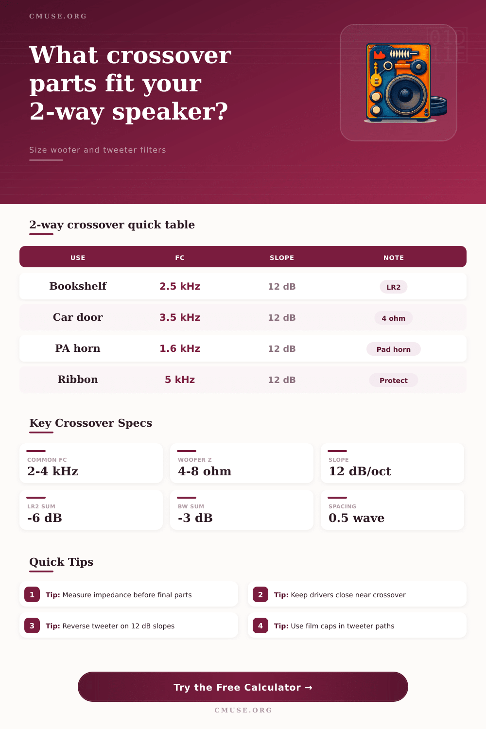
🎯 Typical 2-Way Crossover Ranges
| Speaker Type | Common Fc Range | Common Slope | Design Note |
|---|---|---|---|
| Small desktop 3-4 inch woofer | 3.5-6 kHz | 12 dB/oct | Higher crossover helps tiny woofers beam less severely. |
| Bookshelf 5-6.5 inch woofer | 2-3.2 kHz | 12 dB/oct | Often balances tweeter safety with woofer directivity. |
| Car component door woofer | 2.8-4.5 kHz | 12 dB/oct | Cabin reflections make tweeter level padding especially useful. |
| PA woofer with compression horn | 1.2-2 kHz | 12 dB/oct or steeper | Horn sensitivity usually needs attenuation. |
| Ribbon or planar tweeter system | 3.5-6 kHz | 12 dB/oct or steeper | Protect low-frequency excursion with conservative Fc. |
⚙ Spec Comparison Grid
📋 Preset Comparison Table
| Preset | Impedance | Frequency | Main Use |
|---|---|---|---|
| Bookshelf LR2 | 8 ohm / 8 ohm | 2.8 kHz | General home hi-fi two-way |
| Studio Monitor | 8 ohm / 6 ohm | 2.2 kHz | Lower crossover with a capable tweeter |
| Car Component | 4 ohm / 4 ohm | 3.5 kHz | Door woofer and dash tweeter set |
| PA Horn Pad | 8 ohm / 8 ohm | 1.6 kHz | High sensitivity horn level matching |
| Ribbon Guard | 8 ohm / 8 ohm | 5.2 kHz | Extra tweeter protection margin |
🔧 Component Selection Notes
| Part | Preferred Type | Watch For | Practical Check |
|---|---|---|---|
| Tweeter series capacitor | Film capacitor | Value tolerance and voltage rating | Parallel small caps to hit exact target values. |
| Woofer series inductor | Air-core or low-DCR iron core | DC resistance reducing woofer output | Check DCR against woofer Re, not only nominal ohms. |
| Shunt capacitor | Film or bipolar electrolytic | Heat and tolerance in high-power systems | Use voltage margin above amplifier peak voltage. |
| L-pad resistors | Non-inductive power resistors | Heat in sealed crossover boards | Use calculated dissipation with at least 2x margin. |
A two-way speaker are a speaker that contains two different type of drivers. Each of these driver utilizes a crossover to direct the sound to those individual driver. Each speaker contain both a woofer and a tweeter.
The woofer is a speaker that is designed to play the low frequencies in the sound but often struggle to play high frequencies accurate. The tweeter is a speaker that is designed to play high frequencies but will be broken if it are required to play low frequencies. The crossover ensure that each of these speaker receive the appropriate frequency; the woofer will receive only the low frequencies and the tweeter will receive only the high frequencies.
How Two-Way Speakers Work
If the crossover isnt proper functioning, both the woofers and tweeters can be damage. The first step in building a two-way speaker is to choose the crossover frequency. The crossover frequency is the frequency at which the woofer will transition into the tweeter.
The frequency should of be chose high enough to protect the tweeter but low enough to ensure that the woofer does not begin to beam its sound. If the frequency is too low, the tweeter can be damage. If the frequency is too high, the woofer may produce unnatural sounding sound.
Once you have selected the crossover frequency, you must choose the slope of the crossover. The slope is the rate at which the volume of the sound frequency diminish. A first-order crossover will use one component for each of the speaker but will protect the driver poorly.
A second-order crossover will use more component and ensure that the tweeter is protected from excessively high frequency. Many builder of two-way speaker will choose a 12 dB per octave slope. The sensitivity of each of the speaker must also be consider.
The tweeter will have a higher sensitivity than the woofer. High sensitivity will result in the tweeter being louder then the woofer. An L-pad can be used to even out the sound of each driver.
The L-pad will utilize resistor to even out the sensitivity of the tweeter. This allow the tweeter to be lowered in volume without impacting the tweeter’s impedance. Another factor in the construction of a two-way speaker is driver spacing.
Driver spacing is the distance between the woofer and tweeter on the speaker. If the distance between each of the two driver is too large, the driver can interfere with each other. This can lead to the sound changing based on where the listener is sitting.
Additionally, it may lead to a dip in the frequency response of the speaker. To avoid these issue, the distance between the woofer and tweeter should be as small as possible. Another factor that must be consider is the quality of the electrical component that will make up the crossover.
The component that should be used include capacitor and inductor. Film capacitor should be used in the tweeter because they is more stable than electrolytic capacitor. Air core inductor should be used for the tweeter because they will not saturate like iron core inductor will.
Finally, high resistance inductor will reduce the output of the woofer so they should be avoid and an appropriate inductor choose. Finally, some trial and error will be necessary to complete the two-way speaker. Even with electrical theory and calculation, you cannot fully calculate the behavior of the driver in the speaker cabinet.
The polarity of the tweeter may have to be reverse to ensure that the sound from the woofer and tweeter are seamless. Electrical theory is the start of building the two-way speaker but the device must be listen to to ensure that the woofer and tweeter are working as they should work together. The goal of building a two-way speaker is for the woofer and tweeter to work as one unit.