4 Way Speaker Crossover Calculator
Size passive crossover starting values for sub, woofer, midrange, and tweeter bands using driver impedance, crossover points, alignment, sensitivity, and power headroom.
🎛 Four-Way Presets
🔌 Crossover Inputs
Values are passive electrical starting points. Real drivers need measurement, baffle, enclosure, and acoustic rolloff checks before final component ordering.
📊 Current Spec Snapshot
📐 Starting Band Reference
| Speaker Goal | Sub / Woofer | Woofer / Mid | Mid / Tweeter | Notes |
|---|---|---|---|---|
| Large hi-fi tower | 50-90 Hz | 250-600 Hz | 2.2-3.5 kHz | Keeps bass driver out of vocal range while easing tweeter stress. |
| Studio main monitor | 70-110 Hz | 450-800 Hz | 2.0-3.0 kHz | Useful where mid clarity and controlled directivity matter. |
| PA four-way cabinet | 100-180 Hz | 700-1200 Hz | 3.5-7.0 kHz | Higher splits suit horns and high-output drivers. |
| Car audio front stage | 60-90 Hz | 300-600 Hz | 2.5-4.5 kHz | Door midbass, dash midrange, and tweeter placement often drive choices. |
| Compact monitor | 120-180 Hz | 700-1000 Hz | 3.0-5.0 kHz | Small woofers need higher handoff points to stay clean. |
🧪 Filter Alignment Comparison
| Alignment | Electrical Slope | Summing Behavior | Component Demand | Best Use |
|---|---|---|---|---|
| First order | 6 dB/octave | Wide overlap, shallow phase rotation | Lowest, one reactive part per side | Drivers with very wide clean bandwidth |
| Butterworth | 12 dB/octave | Flat filter magnitude but acoustic summing needs care | Moderate, common passive starting point | General passive prototypes |
| Linkwitz-Riley | 12 or 24 dB/octave | Designed for in-phase acoustic summing at crossover | Moderate to high | Modern measurement-led speaker design |
| Bessel | 12 dB/octave | Gentler amplitude knee, smoother time behavior | Moderate, often needs response correction | Midrange transitions where phase feel matters |
🔊 Driver Band Spec Comparison
| Band | Typical Driver | Usable Range | Crossover Risk | Part Priority |
|---|---|---|---|---|
| Sub / bass | 8-15 inch woofer | 20-150 Hz | Large inductors add resistance and can soften bass control. | Low DCR inductor with enough current rating. |
| Low / woofer | 6-10 inch woofer | 70-1000 Hz | Cone breakup or beaming can color vocals if crossed too high. | Low-pass inductor and high-pass capacitor quality. |
| Midrange | 2-5 inch cone or dome | 300 Hz-5 kHz | Too low a high-pass raises excursion and distortion. | Capacitor tolerance and band-pass symmetry. |
| Tweeter | Dome, ribbon, or horn | 2 kHz-20 kHz | Low crossover points can overheat or over-excurse tweeters. | Film capacitor, padding resistor wattage, protection margin. |
🔧 Practical Component Rounding
| Component | Common Range | Rounding Rule | Series / Parallel Trick | Watch Point |
|---|---|---|---|---|
| Air-core inductor | 0.10-15 mH | Round within 5% when possible | Series adds inductance | DCR changes woofer output and damping. |
| Iron-core inductor | 1-30 mH | Use for large bass coils when current is high | Series adds inductance | Saturation can occur at high power. |
| Film capacitor | 1-100 uF | Prefer close value on tweeter and mid paths | Parallel adds capacitance | Large film values can be bulky. |
| Non-polar electrolytic | 20-300 uF | Useful for large low-frequency caps | Parallel adds capacitance | ESR and tolerance are wider than film. |
| L-pad resistor | 1-50 ohm | Choose wattage above expected dissipation | Series and shunt set attenuation | Heat spacing matters inside sealed boxes. |
📋 Preset Comparison Grid
| Preset | Split Points | Nominal Loads | Power | Design Intent |
|---|---|---|---|---|
| Hi-Fi Tower | 60 / 350 / 2800 Hz | 8 / 8 / 8 / 6 ohm | 160 W | Extended bass with a dedicated lower-mid handoff. |
| Studio Main | 80 / 600 / 2600 Hz | 8 / 8 / 8 / 6 ohm | 180 W | Clean vocal range and lower tweeter stress. |
| PA Cabinet | 120 / 800 / 4500 Hz | 8 / 8 / 8 / 8 ohm | 400 W | High output with horn-friendly upper crossover. |
| Car Front Stage | 70 / 450 / 3500 Hz | 4 / 4 / 4 / 4 ohm | 100 W | Sub, door midbass, dash mid, and tweeter split. |
| Compact Monitor | 150 / 900 / 4000 Hz | 8 / 8 / 8 / 6 ohm | 80 W | Small cabinet with protected small-format drivers. |
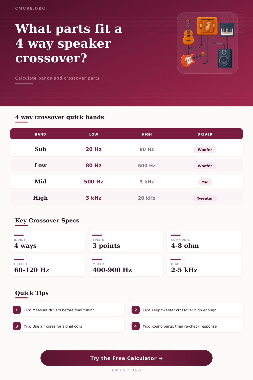
A four-ways speaker system consist of four different driver. A four-way speaker system will require a crossover in order to correct function. If you connect the four drivers directly to an amplifier, the tweeter will receive overlapping frequency that can damage its delicate component.
The crossover are designed to direct specific frequencies to specific driver. For instance, the subwoofer can receive the low frequencies, the woofer can receive the low-mid frequencies, the midrange driver can receive the mid frequencies, and the tweeter can receive the high frequencies. The crossover points are the frequencies at which one of the speaker stops playing and another speaker start to play.
How a Four-Way Speaker Works and How to Tune It
These frequency will determine the performance of the speaker system. For instance, if the woofer is set to a high crossover point, the woofer will experience beaming that narrow the soundstage. If the midrange driver is set to a low crossover point, the driver will move too much air in the speaker.
You can find these points on a reference table so that you can set them on the driver during the tuning process. Filter alignment describe the method in which the drivers transition from one frequency to another. The filter alignment that is select will affect the sound of the speaker system.
For instance, first-order slope allow for many overlap in the drivers. First-order filter will keep the phase shift low. First-order filters, however, offer little protection for the speakers driver.
Another method of filter alignment is the Linkwitz-Riley filter. Linkwitz-Riley filter are designed to produce a flat response at the crossover point between speakers. Linkwitz-Riley filters require more component than a first-order filter.
The advantage of a Linkwitz-Riley filter is that it prevents volume bump in the sound at the crossover point between speakers. If you choose a frequency but not a slope the speaker system will produce a muddy sound. Sensitivity are used to describe how loud each driver can play.
Each driver will have different sensitivity. For instance, the sensitivity of a tweeter will be higher than that of a subwoofer. This means that the tweeter will play at a higher volume than the subwoofer.
If you dont account for the sensitivity in building the system, the high frequencies will seem louder than the lower frequencies. An L-pad can be used to manage the sensitivity of each driver. An L-pad will allow you to even out the sound of each driver so that each play at the same volume.
Impedance are the electrical resistance of the speakers driver. The impedance can change depending on the frequency. The impedance may read 8 ohms on the driver, however this can fluctuate.
Your calculation may not match the actual impedance of the driver. You can measure the impedance of the drivers. This will allow you to understand how the impedance of the driver affect the crossover frequency of the driver.
For example, if there is a peak in the impedance at the crossover frequency, the crossover frequency will change. The crossover filter has a physical construction that require special care when constructing the system. The component in the crossover can interfere with one another.
For instance, if you place inductor and capacitor that are large in size next to one another, they can create magnetic interference with one another. Two large coil mounted in the same orientation will couple with one another. This magnetic coupling will smear the stereo image.
If you rotate the coil so that each is mounted at ninety degrees from the other, the cook will resolve this problem. Building the four-way speaker system involve finding the limits of the drivers, the amplifier, and the room. All of the tool provided will assist with the initial construction of the system.
However, adjustment must be made to achieve the desired sound. Building a speaker system is a process of trial and error to find the best setting for each driver. Trial and error is the only way to ensure that the four drivers sound as a single unit.