Dual Reflex Bandpass Enclosure Calculator
Size a sixth-order bandpass speaker box with two tuned chambers, round port lengths, passband span, chamber ratios, and port-speed checks.
🎵Descriptive dual-reflex presets
🔧Driver, chamber, and port inputs
This calculator uses round-port Helmholtz equations and alignment ratios for early design. Final acoustic response still depends on driver nonlinearities, leaks, wall losses, and port end details.
📊Calculated design snapshot
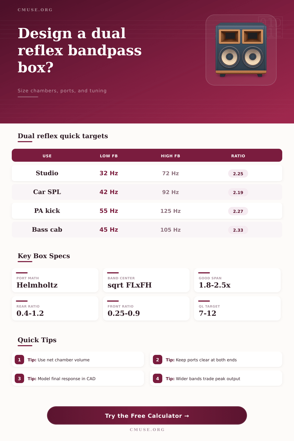
📐Dual-reflex alignment reference
| Alignment goal | FH / FL range | Chamber balance | Typical use |
|---|---|---|---|
| Wide musical bandwidth | 2.2 to 2.8 | Larger rear, moderate front | Home theater, studio sub |
| Compact punch alignment | 1.8 to 2.3 | Smaller chambers, higher tunings | Small drivers, practice systems |
| Maximum narrow output | 1.4 to 1.9 | Tightly controlled front volume | SPL burp, limited band program |
| Instrument reinforcement | 2.0 to 2.5 | Moderate rear loading | Bass guitar, kick drum support |
🎚Port and tuning comparison grid
| Design style | Port count strategy | Strength | Watch item |
|---|---|---|---|
| Single rear, single front round port | One vent per chamber | Simple build and easy trimming | Velocity may rise on small boxes |
| Dual front round ports | One rear, two front | More high-band area | Longer front tubes for same tuning |
| Large slot equivalent | Convert slot area to round diameter | Fits shallow baffles | End correction changes with walls |
| Flared high chamber vents | Use larger effective diameter | Lower turbulence near FH | Flare takes internal volume |
📝Common sixth-order project sizes
| Project | Driver range | Net chamber range | Useful passband |
|---|---|---|---|
| Nearfield studio sub | 8 to 10 in | 18 to 55 L total | 32 to 90 Hz |
| Car cabin SPL enclosure | 10 to 15 in | 45 to 140 L total | 38 to 105 Hz |
| PA kick support cabinet | 12 to 15 in | 70 to 180 L total | 50 to 130 Hz |
| Deep sub reflex rig | 15 to 18 in | 150 to 360 L total | 24 to 75 Hz |
💡Design notes
A sixth-order bandpass enclosure are made up of two separate chambers. The speaker driver is place in between these two chamber. Each of these chambers can be tune to a different frequency.
Because each chamber is tuned to a different frequency, the enclosure act as a filter that focuses the energy of the speaker driver into a specific range of frequency. Standard port box allow for a wide range of frequencies to emanate from the speaker, but the bandpass enclosure limits the frequencies to a specific window. The relationship between the rear and front chamber is the most important in a sixth-order bandpass enclosure.
How a Two-Chamber Bandpass Enclosure Works
The rear chamber is use to provide support for the low-frequency sound created by the speaker driver. The front chamber shape the sound that emanate from the speaker to ensure that the frequencies is within the desired range. To design the enclosure, the designer must calculate the tuning frequency of both the rear and front chamber.
The Helmholtz equation can be used to calculate these frequencies. By entering the specifications of the speaker driver into the calculator, you can calculate the required length of the box ports. The tuning ratio of a sixth-order bandpass enclosure is the difference between the low tuning frequency and the high tuning frequency of the enclosure.
If