Subwoofer Wiring Calculator
Estimate final impedance, amplifier load safety, RMS distribution, current draw, and speaker wire gauge for common SVC and DVC subwoofer wiring layouts.
🔊 Wiring Presets
⚙ Subwoofer Wiring Inputs
📊 Subwoofer Spec Grid
🧮 Wiring Topology Comparison
All Parallel
Lowest impedance. Raises amplifier current and is useful only when the amp is stable at the resulting load.
All Series
Highest impedance. Safer for many amplifiers but usually reduces available RMS power.
Series-Parallel
Balances DVC systems by wiring each sub higher, then combining subs lower at the amplifier.
Parallel-Series
Combines each DVC sub lower, then raises the final load by placing sub groups in series.
📝 Common Final Load Reference
| Subwoofer Set | Coils Used | Parallel Result | Series Result |
|---|---|---|---|
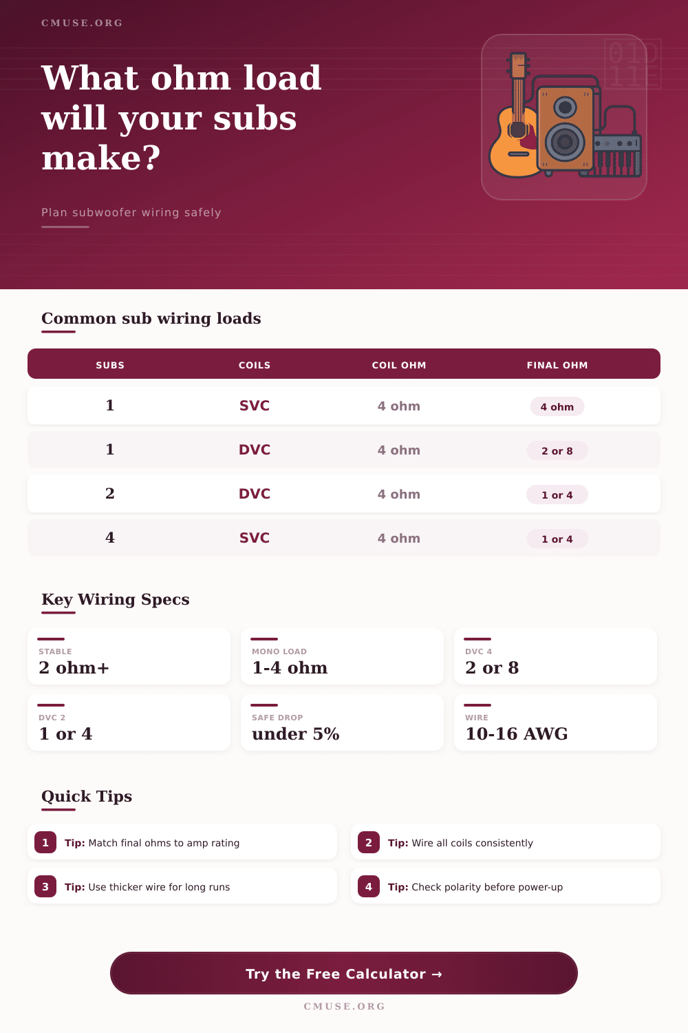
| 1 SVC 4 ohm | 1 total coil | 4 ohms | 4 ohms |
| 1 DVC 4 ohm | 2 total coils | 2 ohms | 8 ohms |
| 2 SVC 4 ohm | 2 total coils | 2 ohms | 8 ohms |
| 2 DVC 4 ohm | 4 total coils | 1 ohm | 16 ohms |
| 4 SVC 4 ohm | 4 total coils | 1 ohm | 16 ohms |
🔌 Speaker Wire Gauge Reference
| AWG | OFC Ohms / 1000 ft | Typical Sub Run | Use Case |
|---|---|---|---|
| 16 AWG | 4.016 | Short, low power | Under 250 W |
| 14 AWG | 2.525 | Most installs | 250-700 W |
| 12 AWG | 1.588 | Longer runs | 700-1500 W |
| 10 AWG | 0.999 | High current | 1500 W+ |
🎚 Amplifier Load Compatibility
| Final Load | Current Demand | Typical Match | Watch Point |
|---|---|---|---|
| 0.5 ohm | Very high | Competition amp | Heat and voltage sag |
| 1 ohm | High | Modern mono amp | Needs strong wiring |
| 2 ohms | Moderate | Daily mono amp | Good power balance |
| 4 ohms | Lower | Bridgeable or home amp | Less RMS output |
📦 Example System Comparison
| System | Drivers | Wiring Target | Typical Result |
|---|---|---|---|
| Sound quality single | 1 DVC 4 | Parallel coils | 2 ohms |
| Daily pair | 2 DVC 4 | Series-parallel | 4 ohms |
| Loud mono pair | 2 DVC 2 | Series-parallel | 2 ohms |
| Four sub wall | 4 DVC 4 | Series-parallel | 2 ohms |
An amplifier may enters protect mode due to the amplifier experiencing an electrical load that is too low for the amplifiers specifications. If the amplifier is in protect mode, the amplifier are attempting to protect it’s self and the speakers from damage. If you push the amplifier to work beyond it’s limits, it will create too much heat for the amplifier to handle.
The heat from the overworked amplifier or speaker coil can lead to failure of either the amplifier or the speaker. Therefore, it is necessary to understand how impedance and heat relates to ensure that the amplifier function apropriately and lasts for a longer period of time. Impedance is the measurement of electrical resistance within the system.
How to Wire Subwoofers and Protect Your Amplifier
For subwoofer with a single voice coil, the impedance is the value label on the subwoofer. However, for subwoofers with dual voice coils, there are different way to wire the voice coils. Each voice coil could be wired in series with the other voice coil or wired in parallel.
Wiring the voice coils in series will increase the impedance of the system. Wiring the voice coils in parallel will decrease the impedance of the system. The total impedance will determine how much power the amplifier will deliver to each subwoofers.
Many people will wire the subwoofers in a parallel configuration to allow the amplifier to deliver more current to the subwoofers. However, if you wire the subwoofers in parallel too much, the impedance will drop too low for the amplifier. An alternative to wiring in parallel is to wire the subwoofers in series.
Wiring in series will increase the impedance of the system and allow the amplifier to run more coolly. However, the total RMS wattage will drop as the impedance increase. Many people make the mistake of buying an amplifier with high power specifications but wiring their subwoofers in a way that make the amplifier work harder then it should and reduces the power delivered to each subwoofer.
To calculate the total impedance of a system with multiple subwoofers, there are calculators available to help determine the total impedance. For systems with subwoofers with individual coils, each coil can be wired in series with the other coils of the same subwoofer. Then the subwoofers can be wired in parallel with each other to the amplifier.
This configuration, known as a series-parallel system, is often use in speaker systems because it allow the speakers to have a stable load of two ohms. The quality of the speaker wire used to connect the amplifier to the subwoofers is another factor in the performance of the amplifier. If the speaker wire has too thin a gauge wire, it will create resistance in the circuit.
This resistance will create heat in the speaker wire before the electrical power reaches the subwoofers. The gauge and material of the wire will affect the electrical current pass through the wire. Using too thin of a gauge of wire can create a voltage drop in the wire, which will make the bass from the speakers sound inconsistently.
Each subwoofer must have the proper polarity to work efficient with each other. Polarity refers to the direction in which the speaker cone vibrate. If one of the subwoofers is wired with an incorrect polarity, the speaker cone will move in the opposite direction of the other subwoofers.
This will cause each of the subwoofers to work against each other, this will cancel the bass that the subwoofers produces. To create an efficient subwoofer system, the amplifier specifications should match the impedance of the subwoofers. Additionally, the speaker wire should be thick enough to carry the electrical current of the subwoofers.
Lastly, you should properly set the polarity of each subwoofer to the amplifier. A subwoofer impedance calculator is available to assist in wiring the subwoofers correctly. It is far easier to change the wiring plan in the calculator than to purchase an amplifier that will be damage once the subwoofers are wired up.