Acoustic Impedance Calculator
Compare acoustic impedance, aperture loading, mass reactance, reflection, and transmission across air, water, tissue, metals, and custom boundaries.
💡 Presets
⚙ Geometry and Medium
Arect = L x W
Acircle = pi x d2 / 4
Atri = 0.5 x base x height
Atotal = count x Ashape
Zarea = Z1 / Atotal
M = rho1 x Lpath / Atotal
Xm = 2 x pi x f x M
R = (Z2 - Z1) / (Z2 + Z1)
T = 4 x Z1 x Z2 / (Z1 + Z2)2
Full breakdown
📘 Reference tables
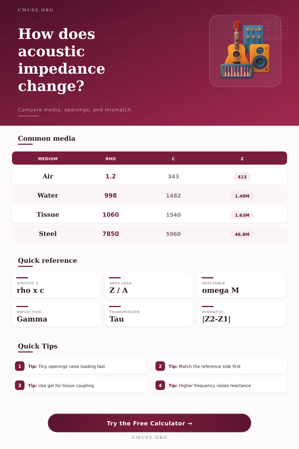
Common media reference
| Medium | rho | c | Z |
|---|---|---|---|
| Air at 20 C | 1.204 | 343 | 413 Rayl |
| Fresh water | 998 | 1482 | 1.48 MRayl |
| Seawater | 1025 | 1505 | 1.54 MRayl |
| Soft tissue | 1060 | 1540 | 1.63 MRayl |
| Acrylic | 1180 | 2730 | 3.22 MRayl |
| Aluminum | 2700 | 6320 | 17.1 MRayl |
| Steel | 7850 | 5960 | 46.8 MRayl |
Interface mismatch guide
| Interface | |R| | T | Read |
|---|---|---|---|
| Air to water | 0.9994 | 0.11% | Near total reflect |
| Air to tissue | 0.9995 | 0.10% | Gel helps a lot |
| Tissue to water | 0.048 | 99.77% | Very close match |
| Water to steel | 0.939 | 11.8% | Strong mismatch |
Geometry and unit guide
| Shape | Area formula | Input pair | Note |
|---|---|---|---|
| Rectangle | L x W | Length, width | Best for slots |
| Circle | pi x d2 / 4 | Diameter | Best for ports |
| Triangle | 0.5 x b x h | Base, height | Best for wedges |
| Custom | Direct input | Area only | Best for measured faces |
Loading and response guide
| Metric | Formula | Units | Why it matters |
|---|---|---|---|
| Specific Z | rho x c | Rayl | Base medium match |
| Aperture load | Z / A | Pa*s/m3 | Smaller area loads more |
| Acoustic mass | rho x L / A | kg/m4 | Longer paths load harder |
| Mass reactance | 2 pi f M | Pa*s/m3 | Frequency raises inertia |
📊 Comparison and spec grid
Acoustic impedance is a property of a medium that determine how sound waves will behave when those sound waves encounter a boundary between two different media. The acoustic impedance of a medium is calculated by multiply the density of that medium by the speed of sound in that medium. The result of this calculation is a value known as specific acoustic impedance, which is measured in rayls.
For example, air has a low specific acoustic impedance of around 400 rayls, water has a specific acoustic impedance of 1.5 million rayls, and steel has an even higher specific acoustic impedance of 47 million rayls. When sound waves travels from one medium to another medium, the difference between the specific acoustic impedances of the two media will cause the sound waves to either reflect off of that boundary between the two media, or to continue to transmit through that boundary. If the specific acoustic impedance values of the two media is very different from one another, most of the sound waves will reflect off of the boundary.
What Acoustic Impedance Is and How It Affects Sound
However, if the specific acoustic impedance values are similar between the two media, most of the sound energy will pass through the boundary. Engineers must consider the properties of acoustic impedance in the design of various devices that utilize sound waves. For instance, engineers must design speakers such that the impedance of the air within the speaker port is not too high, or the sound output of the speaker will be less than desired.
Similarly, ultrasound probes emit sound waves into the body, but the air that exists between the probe and the body has a low specific acoustic impedance compared to the bodys tissue. As a result, most of the sound energy reflects off of the body, preventing the ultrasound waves from entering the body. To overcome this issue, a technician uses coupling gel between the ultrasound probe and the skin, as the coupling gel has a specific acoustic impedance that is similar to the skins.
A calculation tool can be used to calculate the acoustic impedance of a medium and various related parameters without having to perform the calculations manually. To use the tool, the user must enter the density of the medium and the speed of sound within that medium. Additionally, the engineer must also select the medium against which the sound wave will encounter a boundary, and must also enter the geometry of the system…
Such as the path length of sound through a neck or slab, the frequency of sound within the system, and the number of openings in the system. The tool will output the specific acoustic impedance of the medium, the aperture loading of the system, the reflection coefficients, and the transmission coefficients of the system. Aperture loading is a parameter that scales the specific acoustic impedance inversely relative to the total area of the system; aperture loading increases with an increase in the frequency of the sound waves or with an increase in the path length of the sound through the system.
The reflection coefficients indicate the portion of the sound that reflects off of a boundary, while the transmission coefficients indicate the portion of the sound that pass through that boundary. The geometry of a system is one of the factors that will impact the acoustic impedance of that system. Sound can travel through a variety of different shapes, including rectangles, circles, and triangles, as well as arrays of various openings.
For instance, an array of small circular ports will exhibit high aperture loading if the ports are of high frequency, as the acoustic mass of each port will behave as a reactance at that frequency. Aperture loading will increase if the path length of the sound through the system is increased or if the area of the ports is decrease. Conversely, if a system employs various parallel openings, its aperture loading will be diluted; more area is available to distribute the acoustic mass of the system.
The frequency of the sound waves that travel through a system is another important factor that impacts the acoustic impedance of that system. For instance, if the frequency of the sound waves is doubled, the reactance of the system will also be doubled. Subwoofers have large port areas to allow for the movement of low frequencies, while tweeters, which emit sound of high frequencies, have small ports.
The user can alter the frequency of the sound waves with the calculation tool to model the impact of changing frequency on the system. Another factor that engineers must consider is the potential challenges to acoustic impedance at various boundaries. For instance, if sound waves move from a medium of air to a medium of water, the specific acoustic impedance of air is much lower than water’s specific acoustic impedance, meaning that the majority of the sound waves will reflect off of the boundary between air and water.
Only around 0.1% of the sound energy will travel through the boundary. This is one of the reasons that divers is unable to hear the noise created from the movement of objects on the surface of the water. Additionally, sound waves moving from soft tissues to bone will experience a scattering of the ultrasound waves due to the difference in specific acoustic impedance between those two media.
In these cases, engineers may use layers of materials with specific acoustic impedance values in the middle of these two media to act as a compromise between the two media. Other factors to consider when calculating acoustic impedance include the potential for errors introduced through the use of various measurements or assumptions within the calculation. For example, the engineer should enter the geometry of the system with the correct units; densities must remain in metric units, the path length of the sound through the system must be entered, and the aperture loading should be considered in the system design.
Additionally, when working with solids, the longitudinal speeds of sound must be used rather than shear waves. An additional factor to consider when calculating the specific acoustic impedance of air is the impact that the temperature of the air has upon its specific acoustic impedance. If the temperature of the air change by 10 degrees Celsius, the density and the speed of sound in the air will change by a few percent.
These changes in density and speed of sound are sufficient to alter the tuning of a port of a speaker. Finally, it is also important to consider that the frequency of sound may also impact the direction of those sound waves. The assumption of plane waves for sound suggests that the sound waves will be normally incident upon a boundary; this is true for narrow beams of sound, but may not be true for sound waves that enter a room at grazing angles to the floor.
Additionally, if the apertures in a speaker are very small, the sound will experience viscous losses; these losses to sound energy increase the resistance of the sound movement in the system beyond what the reactance calculations suggest.