Line Level Crossover Calculator
Size RC, Sallen-Key, and Linkwitz-Riley line-level stages, then verify component pairs, stage Q, gain, and source/load margin before you build.
📈Preset Crossover Paths
Pick a preset, then adjust the exact frequency, component choice, and rounding series if you want a tighter build match.
🔧Calculator Inputs
SK2: K = 3 - 1 / Q, then Rf = (K - 1) x Rg
LR4: two Butterworth 2nd-order stages at the same fc
Headroom: dBu = 20 log10(Vrms / 0.775)
Full breakdown
📊Reference Spec Grid
📑Reference Tables
Topology comparison
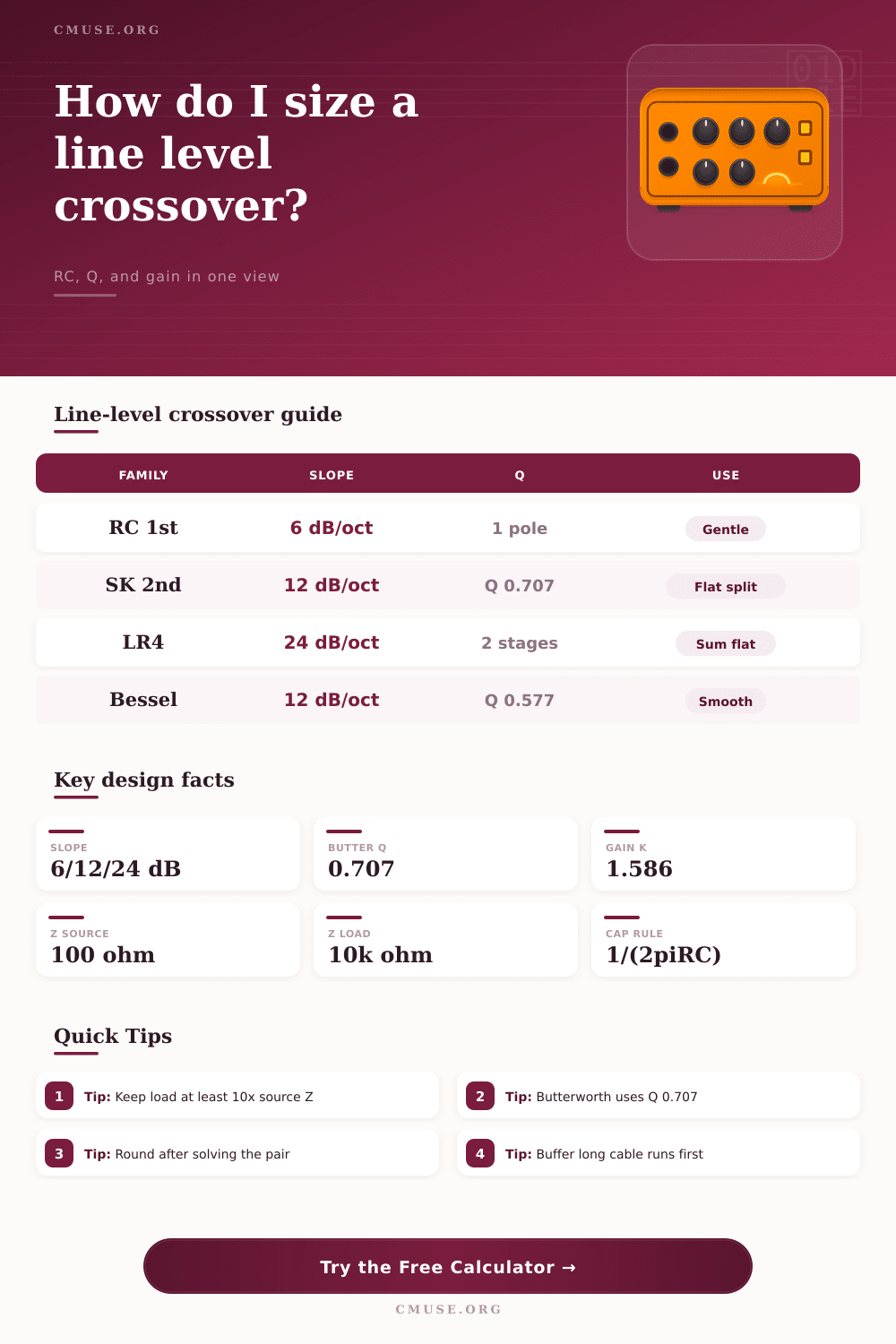
| Family | Slope | Q | Best use |
|---|---|---|---|
| RC 1st | 6 dB/oct | 0.5 | Rumble cut |
| SK 2nd | 12 dB/oct | 0.707 | Flat split |
| LR4 | 24 dB/oct | 0.707 | Summed flat |
| Bessel 2nd | 12 dB/oct | 0.577 | Soft phase |
Line impedance guide
| Role | Typical Z | Target load | Note |
|---|---|---|---|
| Consumer out | 100-600 | 10k+ | Good margin |
| Pro out | 50-200 | 10k-47k | Stable cutoff |
| Line in | 10k-100k | High Z | Easy drive |
| Buffer | Low Z | Long cable | Less loss |
Common crossover targets
| Split | Range | Family | Why |
|---|---|---|---|
| Sub / sat | 60-90 Hz | LR4 | Tight bass |
| Woofer / tw | 1.8-3.5 kHz | LR4 | 2-way norm |
| Midbass / mid | 120-250 Hz | SK2 | Compact box |
| Rumble cut | 15-35 Hz | RC1 | Subsonic fix |
Component series quick chart
| Series | Tolerance | Use | Default |
|---|---|---|---|
| Ideal | Exact | Math only | No rounding |
| E12 | 10% | Quick build | Loose fit |
| E24 | 5% | Audio norm | Best default |
| E96 | 1% | Precision | Matched pair |
💡Tip Boxes
A line-level crossover divide the audio signal into different frequency bands and sends those specific frequencys to specific speaker. The line-level crossover are placed between the preamplifier and the power amplifier to process the signal before it reach the power amplifier. A line-level crossover works at line level to manage the voltage in the signal that typically range between 1 and 2 volts RMS.
Since a line-level crossover is working at line level, it dont have to worry about the physical movement of the speakers coils or cones. A line-level crossover use two primary type of filters: a low-pass filter and a high-pass filter. A low-pass filter will allow the low frequencies to pass through the filter and send them to a subwoofer.
How a line-level crossover works
The high-pass filter will allow the high frequencies to pass through the filter and send them to the satellite speaker. The components of a line-level crossover include resistors and capacitors to create the low-pass and high-pass filters. These components will create poles in the line-level crossover that will change the frequency response of the signal.
A single pole will create a 6 dB per octave slope. Creating two poles will create a 12 dB per octave slope. Creating four pole will create a 24 dB per octave slope.
A 24 dB per octave slope is referred to as a Linkwitz-Riley filter. Using a Linkwitz-Riley filter will allow the low and high frequencies to combine to create a flat frequency response. Impedance is another important factor to consider in a line-level crossover.
The impedance needs to be managed so that the cutoff frequency do not change. The source impedance must be much lower than the load impedance. A common rule of thumb is that the source impedance should be 10 times lesser than the load impedance.
If the impedance margin is too large, the target frequency will drift from the target frequency. This drift in frequency will cause the sound of the audio to sound incorrect. For instance, if the target frequency is 80 Hz but the frequency drift to 75 Hz, the bass will sound incorrect.
Active stages can also be used to control the Q factor. The Q factor determine the shape of the frequency response. A Butterworth filter will have a Q factor of 0.707, and a Bessel filter will have a Q factor of 0.577.
The resistors and capacitors that are use in a line-level crossover must meet the mathematical requirement of the filter. For instance, the mathematical formula to calculate the values of the component is 1 divided by 2 multiplied by pi multiplied by resistance multiplied by capacitance. Instead of using the mathematical calculation, it is easiest to use a standard component series for the capacitors and resistors.
A common component series to use is the E24 series. The larger the tolerance for the components, the less accurately the frequency will be. For example, the E12 series have a 10 percent tolerance for the components.
Using the E24 series will limit the components to a 5 percent tolerance. Five percent is more accurate for the line-level crossover than 10 percent. Additionally, the voltage levels of the audio signal must be within the limits of the operational amplifier in the line-level crossover.
If the voltage is too high for the operational amplifiers, the amplifier will clip the signal. When building a line-level crossover, it is important to avoid some common mistake. One mistake is connecting a long cable before the line-level crossover.
Connecting a long cable to the signal before the line-level crossover can cause the cutoff frequency of the signal to wander. An active buffer should be placed before the line-level crossover to ensure the output impedance of the signal are low. Using a buffer will ensure the line-level crossover remain stable in the signal chain.
Another mistake when building a line-level crossover is to fail to match the gain of each path of the line-level crossover. Using different gain along each path of the line-level crossover will cause one path to be louder then the other path. One last mistake to avoid when building a line-level crossover is failing to check the headroom of the operational amplifiers.
Some circuits in a line-level crossover will increase the peak voltage of the signal. Increasing the peak voltage of the signal increase the amount of headroom that is required of the operational amplifiers.