Line Level L-Pad Calculator
Design a resistive line pad for clean attenuation, then check how the series and shunt parts affect impedance, voltage loss, and resistor power.
🎚Quick Presets
⚙Pad Inputs
Calculation results
📊Line Pad Spec Grid
Common line level standards
| Standard | Nominal | Vrms | Use |
|---|---|---|---|
| Consumer | -10 dBV | 0.316 | Home gear |
| Professional | +4 dBu | 1.228 | Studio line |
| Hot pro | +18 dBu | 6.156 | Peak headroom |
| Broadcast | +24 dBu | 12.283 | Console out |
Attenuation ratio guide
| dB | k | Power | Note |
|---|---|---|---|
| 3 dB | 0.708 | 0.50x | Small trim |
| 6 dB | 0.501 | 0.25x | Half voltage |
| 10 dB | 0.316 | 0.10x | Noticeable cut |
| 20 dB | 0.100 | 0.01x | Strong pad |
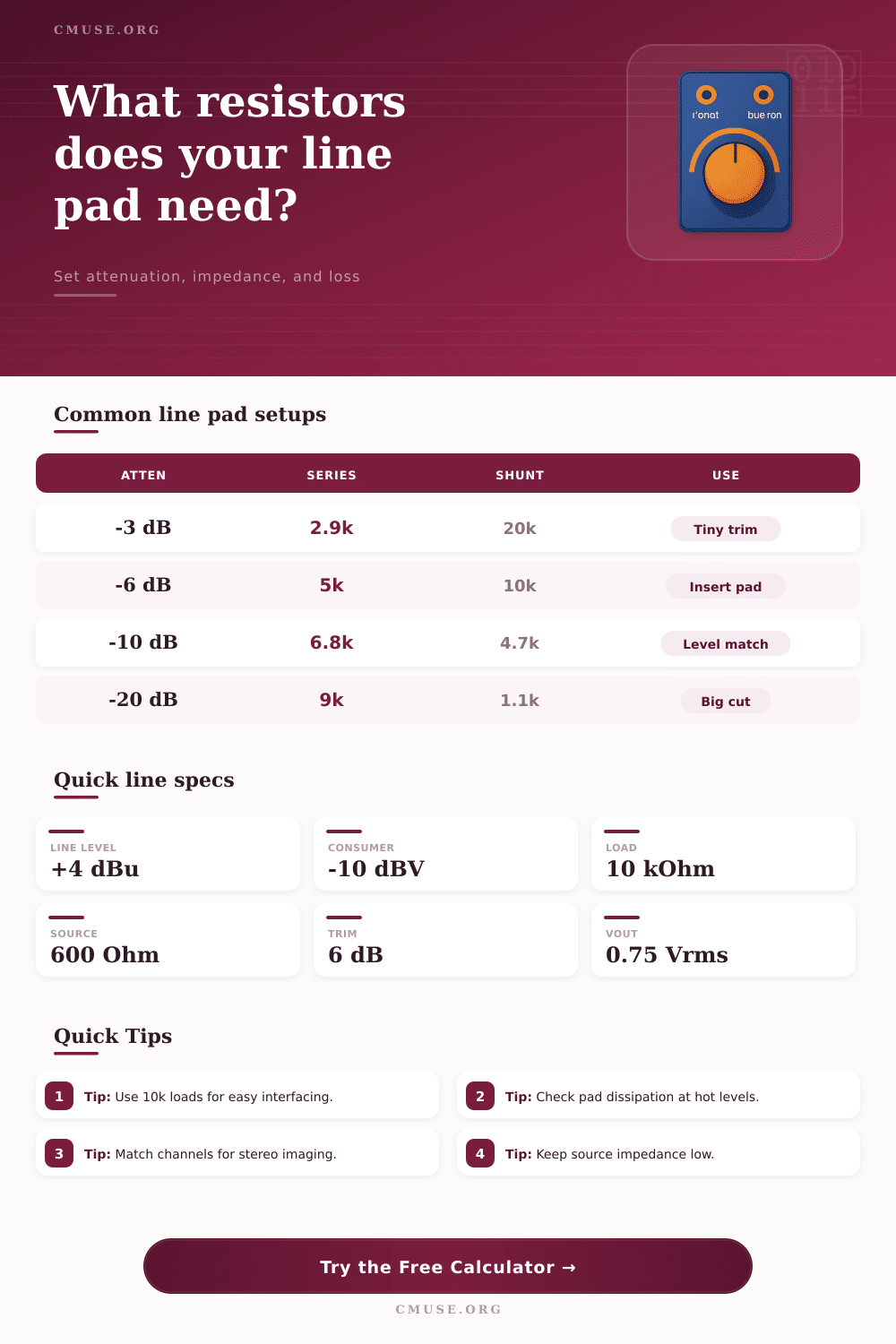
Classic 10k L-pad examples
| Atten | Series | Shunt | Use |
|---|---|---|---|
| 3 dB | 2.9k | 20k | Gentle trim |
| 6 dB | 5k | 10k | Normal pad |
| 10 dB | 6.8k | 4.7k | Hot source |
| 20 dB | 9k | 1.1k | Big cut |
Source and load guidance
| Source | Rsource | Load | Note |
|---|---|---|---|
| DAC | 100 ohm | 10k | Easy drive |
| Mixer out | 200 ohm | 10k | Standard feed |
| Line out | 600 ohm | 10k | Legacy gear |
| Broadcast | 150 ohm | 47k | Long cable |
🔧Practical Notes
An L-pad is a tool that can used to reduce the voltage of an audio signal. An L-pad is used when the signal that is to be reduced in voltage is too hot for the input of the receiving audio equipment. An L-pad consists of two resistor that are arranged in an L shape in the circuit schematic for the audio equipment.
One resistor will be a series resistor that is placed in the audio signal path, and the other resistor will be a shunt resistor that is placed in parallel with the signal path and to ground. Because both types of resistors is included in the L-pad circuit, the L-pad is able to reduce the voltage of the audio signal while maintaining the impedance of the audio equipment that utilize the L-pad. Impedance matching is important in the implementation of an L-pad.
What an L-pad Does and How It Works
Impedance matching ensures that the signal source and the receiving equipment work together correctly. If the series resistor has too high of a value, the impedance of the equipment will decreases. Additionally, if only a series resistor is used, without the shunt resistor, there is no control over the load resistance of the signal source.
In order to achieve the correct attenuation of the signal, the resistors in the L-pad must have the correct values to allow for proper impedance within the audio equipment. Audio signals can contain a variety of different voltage levels. The various voltage level require different settings in the L-pad.
For example, professional audio equipment typically has voltage levels of +4 dBu, while consumer audio equipment has voltage levels of –10 dBV. An L-pad can help to bridge the gap between these different voltage levels. However, it is important for the engineer to account for the output impedance of the audio signal source.
If the output impedance is ignored, the engineer will not achieve the calculated attenuation of the signal with the L-pad. In addition to the output impedance of the signal source, the input impedance of the receiving equipment should also be considered when implementing an L-pad. Power dissipation is another factor to consider in the implementation of an L-pad.
Power dissipation is a measurement of the amount of heat that the resistors in the L-pad create. At low line voltage levels, the resistors will dissipate little heat. However, high voltage signals will cause the resistors to dissipate more heatly.
If the resistors are not rated to handle the amount of power in the signal, they may overheat and fail. In these situations, it is better to use resistors with a higher power rating, such as half-watt resistor. Lastly, another consideration is for stereo signals.
Each channel in the stereo signal should have the same resistance to ensure that the center image of the stereo signal is not distort. To ensure that each channel has the same resistance, it is necessary to use resistors with tight tolerances, such as 1 percent tolerance resistors. There are a variety of ways to use an L-pad in audio equipment.
For instance, a 10 dB L-pad can be used to allow for a professional audio signal to be sent to a consumer audio equipment. Additionally, a 20 dB L-pad can be used to allow audio signals from effects return to the mix. Because the various audio sources can contain different impedances, a 10 dB L-pad, for instance, may not work for all audio equipment.
For instance, digital to analog converter have low impedances, while other audio equipment like legacy audio equipment have higher impedances. As such, the correct value for an L-pad must be chosen based on the impedance of the signal source. If the wrong value is selected for the L-pad, the voltage ratio will not be correctly.